
Turn-on accumulator apparatus

A technology of accumulator and pressing device, which is applied to the power device, contacts, electrical components and other directions inside the switch, and can solve the problem of high cost

Active Publication Date: 2010-12-22
SIEMENS SWITCHGEAR LTD SHANGHAI
View PDF6 Cites 0 Cited by
  • Summary
  • Abstract
  • Description
  • Claims
  • Application Information

AI Technical Summary

Problems solved by technology

Such lost motion bearings are precision components and are therefore very expensive

Method used


Image

  • Turn-on accumulator apparatus
  • Turn-on accumulator apparatus
  • Turn-on accumulator apparatus

Examples


Embodiment Construction

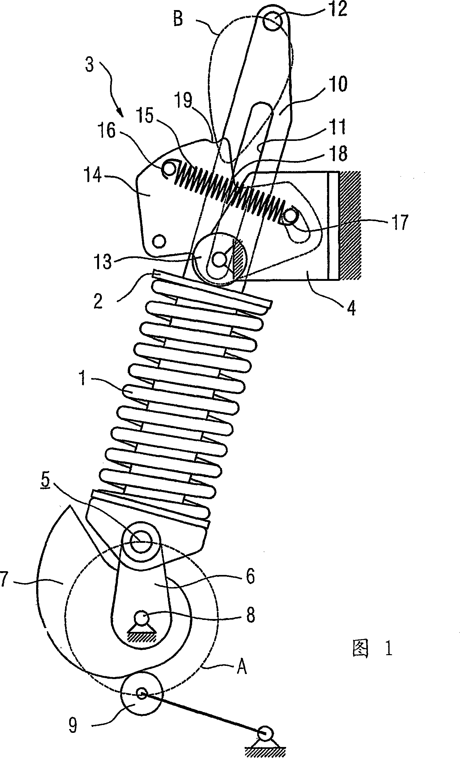
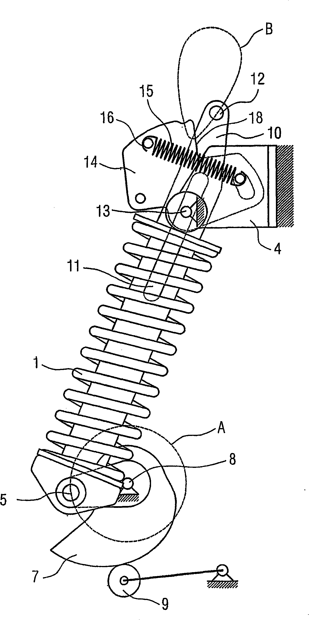
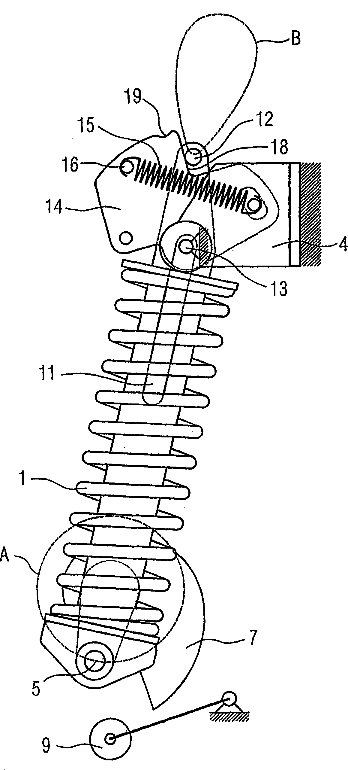
[0016] figure 1 The switch-on accumulator arrangement is shown with a spring element 1 as switch-on accumulator, which is connected at a first end 2 to the fixing part 4 by means of a ratchet arrangement 3 and at a second end 5 to the eccentric The wheels 6 are hingedly connected. The eccentric 6 and the cam 7 are fixedly arranged on the pressing shaft 8 . The cam 7 cooperates with a switching shaft 9, which is part of an actuating mechanism, not shown, for disconnectable switching contacts of the circuit breaker. A guide part 10 with an elongated hole 11 and a stop element 12 is guided through the first end 2 of the switch-on energy store 1 . The guide part 10 is rigidly connected to the second end 5 and is supported on the fixed part 4 by means of a shaft 13 extending through the elongated hole 11 . The ratchet device 3 comprises a pawl 14 , also rotatably supported on the shaft 13 , and a spring 15 , the first end 16 of which is fastened to the pawl 14 and the second end...


PUM


Abstract

In order to form a switch-on energy store apparatus for a circuit breaker, wherein a switch-on energy store (1) is held at a first end (2) and is connected to a cam (6) of a tensioning apparatus at a second end, with which tensioning apparatus means interact which limit a return movement, which switch-on energy store apparatus has a simple and cost-effective design, the invention proposes that the means have a ratchet mechanism arranged at the first end of the switch-on energy store.

Description

technical field [0001] The invention relates to a switch-on accumulator device for a circuit breaker, wherein the switch-on accumulator is fastened at a first end and is connected at a second end to an eccentric of a pressing device, which is connected to a limiter Device interaction to reset motion boundaries. Background technique [0002] Such a switch-on energy storage device for a circuit breaker is known from DE 19503697 C1. The switch-on spring as switch-on accumulator is fastened at its first end and is connected at its second end to an eccentric which is arranged on the pressing shaft and the switching shaft. In the clamping device for switching on the spring, the return stop is designed as a device that defines the limit of the reset movement; the return stop has a stop element and a freewheel bearing ( Freilauflager). In this case, the sleeve is decoupled from the lift shaft via a lost bearing during the clamping process. After the switch-on process of the circ...

Claims


Application Information

Patent Timeline
Patent Type & Authority Patents(China)
IPC IPC(8): H01H3/30
CPCH01H2001/508H01H3/3021
Inventor 卡斯滕·弗罗因特
Owner SIEMENS SWITCHGEAR LTD SHANGHAI
Learn More