Fiber enhanced composite material annularly coated printing nozzle

A composite material and fiber-reinforced technology, applied in the direction of additive processing, additive processing of mixtures of solid materials and liquid materials, processing and manufacturing, etc., can solve the internal structure and thermal distribution of the limited nozzle, affect the mechanical properties of printed parts, Problems such as poor fiber and resin infiltration effect, to achieve the effect of increasing flow rate and flow rate, improving mechanical properties, and reducing porosity

Active Publication Date: 2019-04-02
ADVANCED MFG TECH CENT CHINA ACAD OF MASCH SCI & TECH
View PDF4 Cites 9 Cited by
  • Summary
  • Abstract
  • Description
  • Claims
  • Application Information

AI Technical Summary

Problems solved by technology

The existing technology mainly feeds continuous fiber and resin wire into the nozzle respectively, and the resin is heated and melted and then mixed with fiber impregnation, limited by the internal structure and thermal distribution of the nozzle, the infiltration effect of fiber and resin is poor, and the fiber is easily absorbed Resin flow scours away wear and directly affects the mechanical properties of printed parts
In addition, the main material of the existing continuous fiber reinforced composite 3D printing technology is the wire that needs to be formed in the early stage. The complicated wire forming process and the limited wire size directly restrict the further improvement of the 3D printing efficiency. Therefore, a new type of 3D printing is developed. It is very urgent to print nozzles for fiber-reinforced composite materials that can adapt to granular and powder printing and have excellent molding mechanical properties.

Method used


Image

  • Fiber enhanced composite material annularly coated printing nozzle
  • Fiber enhanced composite material annularly coated printing nozzle
  • Fiber enhanced composite material annularly coated printing nozzle

Examples


Embodiment Construction

[0020] The technical solutions in the embodiments of the present invention will be clearly and completely described below in conjunction with the accompanying drawings in the embodiments of the present invention. Obviously, the described embodiments are only a part of the embodiments of the present invention, not all the embodiments. The following description of at least one exemplary embodiment is actually only illustrative, and in no way serves as any limitation to the present invention and its application or use. Based on the embodiments of the present invention, all other embodiments obtained by those of ordinary skill in the art without creative work shall fall within the protection scope of the present invention.

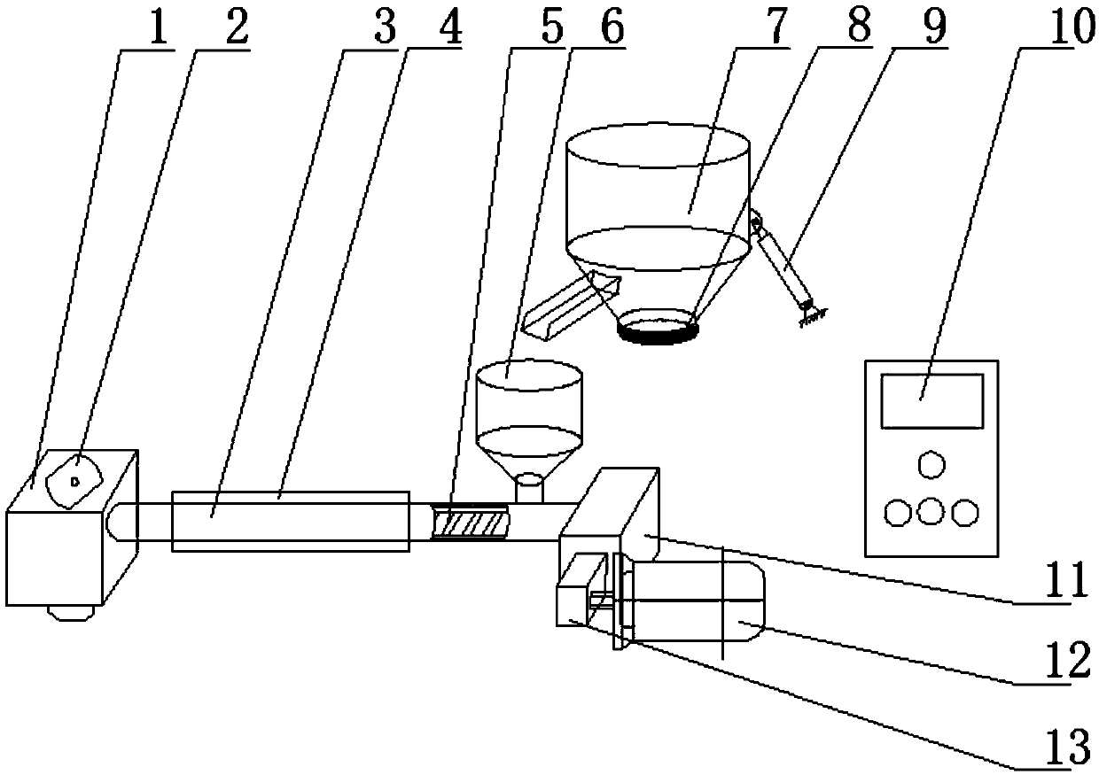
[0021] Reference figure 1 As shown, a fiber-reinforced composite material ring-shaped coating printing nozzle includes a feeding part, an extrusion mechanism (3), a dipping chamber (1), a ring-shaped coating nozzle (2), a measurement and control part (10) , And f...


PUM


Abstract

The invention relates to the technical field of 3D printing and provides a fiber enhanced composite material annularly coated printing nozzle. The fiber enhanced composite material annularly coated printing nozzle comprises a feeding part, an extruding mechanism, an impregnating cavity, an annularly coated nozzle and a measuring and controlling part, wherein the feeding part is primarily used forproviding a resin material quantitively at a constant speed and the lower end of the feeding part is connected to the extruding mechanism; the resin is extruded at the constant speed under the actionof a heating ring and a screw to enter the impregnating cavity; in the impregnating cavity, the resin and the fibers are mixed and are extruded and formed through the annularly coated nozzle. The bottom end of the annularly coated nozzle is of a planar structure. The formed surface can be compacted after the composite material is formed, so that the inner porosity is reduced, and the laminar bonding effect is improved. In the printing process, a plurality of temperature and pressure parameters need to be collected and controlled. The printing nozzle mixes the resin and the fibers quickly and efficiently on the one hand, and compacts and prints the resin and the fibers on the other hand, so that the mechanical property of a formed part can be improved.

Description

Technical field [0001] The invention belongs to the field of composite 3D printing (additive manufacturing), and relates to a fiber-reinforced composite material ring-shaped coating printing nozzle. Background technique [0002] 3D printing (additive manufacturing) technology is a method of forming three-dimensional parts by stacking layers of materials. Compared with the traditional subtractive manufacturing, this method improves the geometric accuracy of processing on the one hand, and greatly reduces the waste of materials on the other hand. In addition, this method can also realize intelligent and digital processing and manufacturing, and improve the efficiency of the part trial production link. [0003] Fiber-reinforced composite materials have the characteristics of good mechanical and chemical properties, recyclability and low density, and their applications in the aviation industry and automobile manufacturing are becoming more and more extensive. For this reason, some sc...

Claims


Application Information

Patent Timeline
Patent Type & Authority Applications(China)
IPC IPC(8): B29C64/165B29C64/20B29C64/209B29C64/393B33Y30/00B33Y50/02
CPCB29C64/165B29C64/20B29C64/209B29C64/393B33Y30/00B33Y50/02
Inventor 单忠德范聪泽战丽刘丰刘晓军
Owner ADVANCED MFG TECH CENT CHINA ACAD OF MASCH SCI & TECH
Why Eureka
Try Eureka