Meter device

A technology for instruments and substrates, which is applied in the field of fixing the substrate to the shell, can solve problems such as sloshing and abnormal sound, and achieve the effect of preventing sloshing and completing manufacturing at a low cost

Inactive Publication Date: 2008-10-15
CALSONIC KANSEI CORP
View PDF1 Cites 7 Cited by
  • Summary
  • Abstract
  • Description
  • Claims
  • Application Information

AI Technical Summary

Problems solved by technology

[0008] Therefore, when the board is mounted on a vehicle, there is a problem that abnormal noise may be generated due to rattling of the gap when vibration is input.

Method used


Image

  • Meter device
  • Meter device
  • Meter device

Examples


Embodiment 1

[0033] Below, based on figure 1 ~ Fig. 9 illustrates the meter device A of Example 1 of the best embodiment of the present invention.

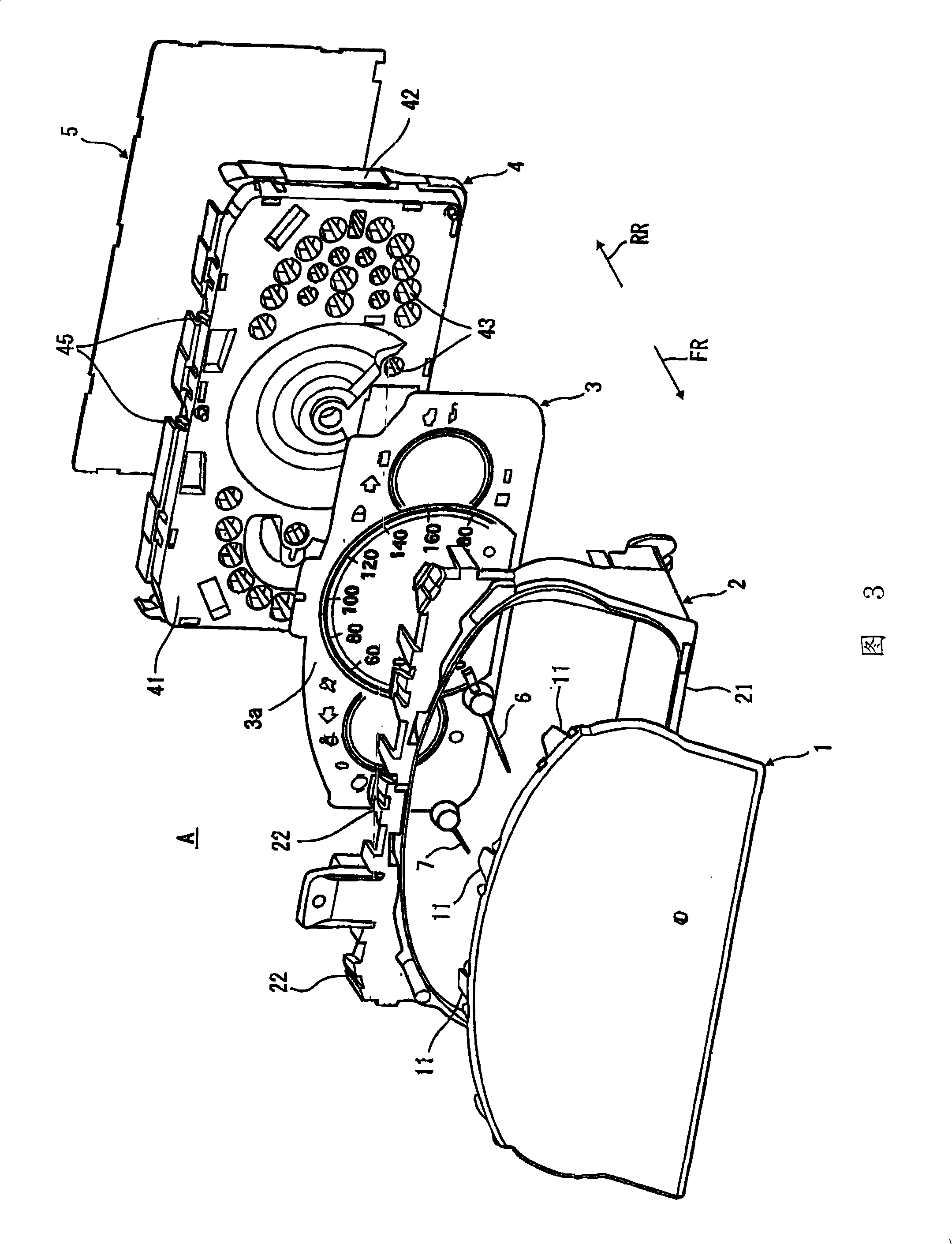
[0034] The instrument device A of the present embodiment 1 is installed in an integrated instrument panel provided on an automobile instrument panel not shown in the figure. As shown in FIG. Shell 2 , letter board 3 , lower shell 4 , base plate 5 .

[0035] In addition, the structure of the meter device A is: the dial plate 3 is interposed between the upper case 2 and the lower case 4, the upper case 2 and the lower case 4 are engaged, and the upper case is covered with a transparent surface cover 1. On the side of the housing 2 facing the front of the meter, a base plate 5 is fixed along the direction of the back of the meter (arrow RR direction) of the lower case 4 .

[0036] The face cover 1 is formed of a transparent resin plate, and a plurality of locking claws 11 integrally formed protruding in the direction of the back of the instrume...

Embodiment 2

[0105] Next, based on Figure 10 The meter device B of Example 2 of the embodiment of the present invention will be described. In addition, this second embodiment is a modified example of the first embodiment, so only the difference will be described, and the description of the same structure and operation effect as the first embodiment will be omitted.

[0106] The meter device B of the second embodiment is an example in which the base plate 205 is pressed and fixed to the lower case 204 with a back cover.

[0107] Such as Figure 10 As shown, the meter device B has a surface cover 201 , an upper case 202 , a dial 203 , a lower case 204 , a base plate 205 , a light guide member 206 , and a back cover 207 .

[0108] In addition, the respective pointers 6 a , 6 b , 6 c , and 6 d are driven by devices 251 , 251 , 251 , and 251 mounted on the substrate 205 .

[0109] The surface cover 201 , the upper case 202 , and the dial 203 are the same as those in the first embodiment, an...


PUM


Abstract

A meter device includes a dial having a display design, a case which is disposed on one side of the dial, and supports the dial, a substrate which is disposed on a side of the case opposite to the dial, the substrate being provided with an electric component for display driving of the dial, a plurality of engagement claws each of which is raised toward the substrate from an outer circumferential portion of the case, and is formed to be elastically deformable in inward and outward sides of the case, and a claw part which projects in an inward direction of the case from a leading end part of the engagement claw, and has an engaging face engaging with an outer circumferential edge portion of the substrate from a side of the substrate opposite to the case side, so as to fasten the substrate to the case.

Description

technical field [0001] The invention relates to an instrument device used in automobiles, and in particular to a technique for fixing a base plate on a casing. Background technique [0002] Conventionally, in meter devices for vehicles, etc., a board is provided on the back side of the dial (the back side of the meter), and electrical components such as a device for driving the pointer and a light source for illuminating the dial from the back side are mounted on the board. . [0003] As a technique for fixing the substrate to the case supporting the dial, there is known a technique in which a cover is provided on the meter back side of the substrate, and the cover is fixed to the case in a state where the substrate is pushed by the cover (for example, Refer to Patent Document 1). [0004] Also known is an economically advantageous technique of omitting the cover and engaging the outer peripheral portion of the substrate with a claw portion of a locking claw rising from th...

Claims


Application Information

Patent Timeline
Patent Type & Authority Applications(China)
IPC IPC(8): G01D13/00B60K37/00
CPCG01D11/24
Inventor 小池仁
Owner CALSONIC KANSEI CORP
Why Eureka
Try Eureka