
Phase insulator

A technology of interphase insulators and insulating sheets, which is applied in the direction of winding insulation materials, winding insulation shape/style/structure, etc., and can solve problems such as inability to ensure interphase insulation at coil ends

Inactive Publication Date: 2008-10-15
TOYOTA IND CORP
View PDF2 Cites 5 Cited by
  • Summary
  • Abstract
  • Description
  • Claims
  • Application Information

AI Technical Summary

Problems solved by technology

Thus, when the interphase insulator is removed from the stator coils, the interphase insulation between the coil ends cannot be ensured

Method used


Image

  • Phase insulator
  • Phase insulator
  • Phase insulator

Examples


Embodiment Construction

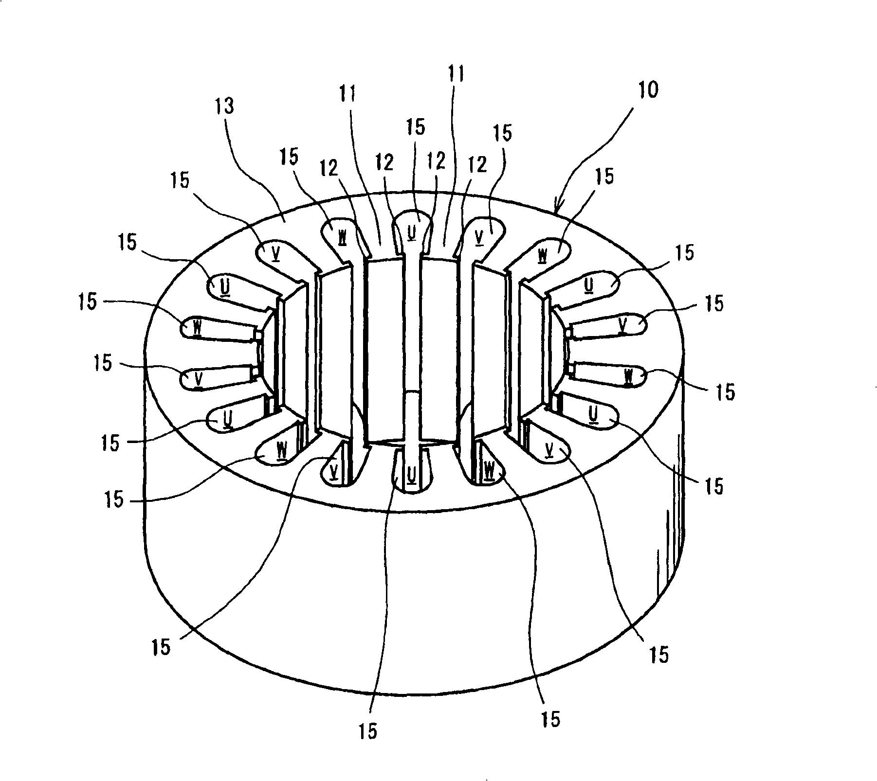
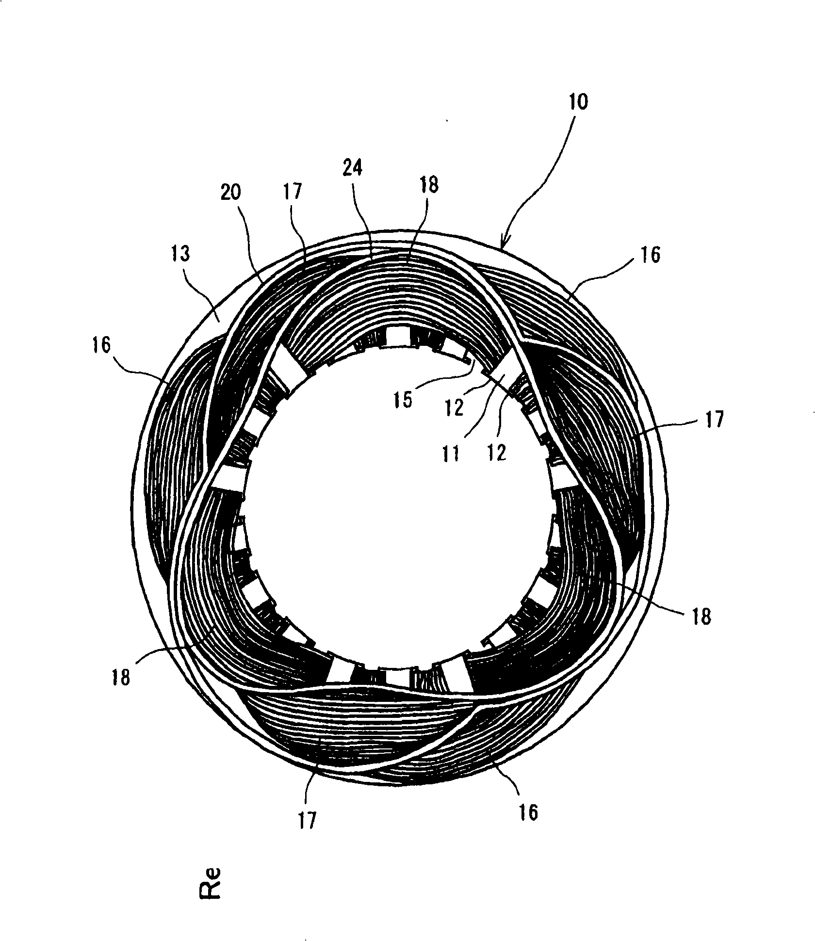
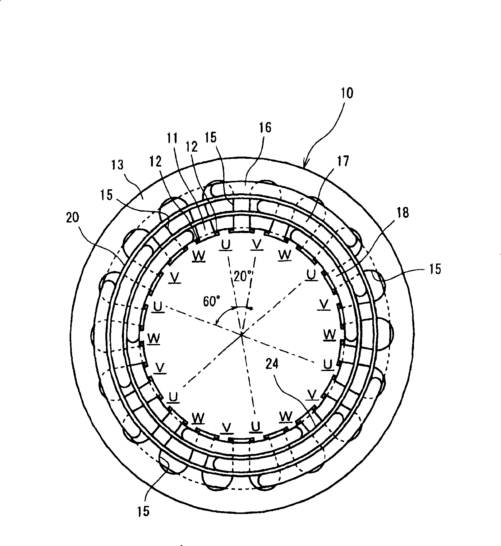
[0016] The following will refer to Figures 1 to 6 A preferred embodiment according to the present invention is described. In this preferred embodiment, the stator core of the stator is incorporated into an electric motor with three-phase distributed windings for an electric compressor. Such as figure 1 As shown, the stator core 10 is formed in a substantially cylindrical shape. The stator core 10 has end surfaces 13 , 14 at both axial end sections, respectively. The end surfaces 13 , 14 are perpendicular to the axial direction of the stator core 10 . figure 1 is a perspective view, and figure 1 The end surface 13 is shown in . The teeth 11 are formed on the inner peripheral surface of the stator core 10 and are arranged in the circumferential direction of the stator core 10 . The teeth 11 protrude toward the axial center of the stator core 10 .

[0017] Each tooth 11 has a protruding portion 12 on both sides of its tip. The protruding portion 12 protrudes in the circu...


PUM


Abstract

The present invention provides a phase insulator for a stator of a motor, which insulates between stator coils. The stator has plural stator coils inserted in slots in a stator core. The phase insulator insulates stator coils from each other. The phase insulator includes insulating sheet portions and bridge portions. The insulating sheet portions are disposed at both end portions of the stator core for insulating between the coil ends of the stator coils. The insulating sheet portions are made of a first material. The bridge portions connect the insulating sheet portions. The bridge portions are inserted in the slots of the stator core. The bridge portions are made of a second material. The second material has higher elastic characteristics than the first material.

Description

technical field [0001] The present invention relates to an interphase insulator, and more particularly, to an interphase insulator having an insulating sheet portion and a bridge portion for connecting the insulating sheet portions. The insulating sheet portion is provided at both ends of the stator core for insulation between coil ends of the stator coil. The bridge sections are inserted into the slots between the teeth of the stator core. Background technique [0002] Generally, a plurality of stator coils are inserted into slots of a stator core of an electric motor. The coils are arranged such that they have different phases with respect to each other. Coil ends of the respective coils mounted on the stator core protrude on both axial end surfaces of the stator core. The coil ends are arranged such that they overlap each other in the radial direction. Sheet-shaped interphase insulators are placed between coils of different phases to insulate the coils. In recent yea...

Claims


Application Information

Patent Timeline
Patent Type & Authority Applications(China)
IPC IPC(8): H02K3/34H02K3/30
CPCH02K3/38
Inventor 上辻清深作博史平野泰三猪饲健介浜名祥三
Owner TOYOTA IND CORP
Learn More