Flexible battery, method for manufacturing same, and auxiliary battery comprising same

Pending Publication Date: 2021-02-11
AMOGREENTECH CO LTD
View PDF0 Cites 0 Cited by
  • Summary
  • Abstract
  • Description
  • Claims
  • Application Information

AI Technical Summary

Benefits of technology

[0025]In a flexible battery of the present invention, there is an effect in that cracks do not occur in a current collector and/or an active material even when a pattern is formed with high strength so as to enhance flexible characteristics.
[0026]Further, an occurrence of cracks can be prevented even when bending occurs as a predetermined pattern is formed, and degradation of

Problems solved by technology

However, since the cylindrical lithium ion battery using a metal can as a container has a fixed shape, there is a disadvantage of limiting a design of an electrical product and it is difficult to reduce a volume.
Specifically, as mentioned above, since the mobile electronic devices are developed to be thinned and miniaturized as well as being flexible, there is a problem in that the conventional lithium ion battery using the metal can or a battery having a prismatic structure is not easy to apply to the above-described mobile electronic devices.
However, a pouch-type battery whic

Method used


Image

  • Flexible battery, method for manufacturing same, and auxiliary battery comprising same
  • Flexible battery, method for manufacturing same, and auxiliary battery comprising same
  • Flexible battery, method for manufacturing same, and auxiliary battery comprising same

Examples


example 1

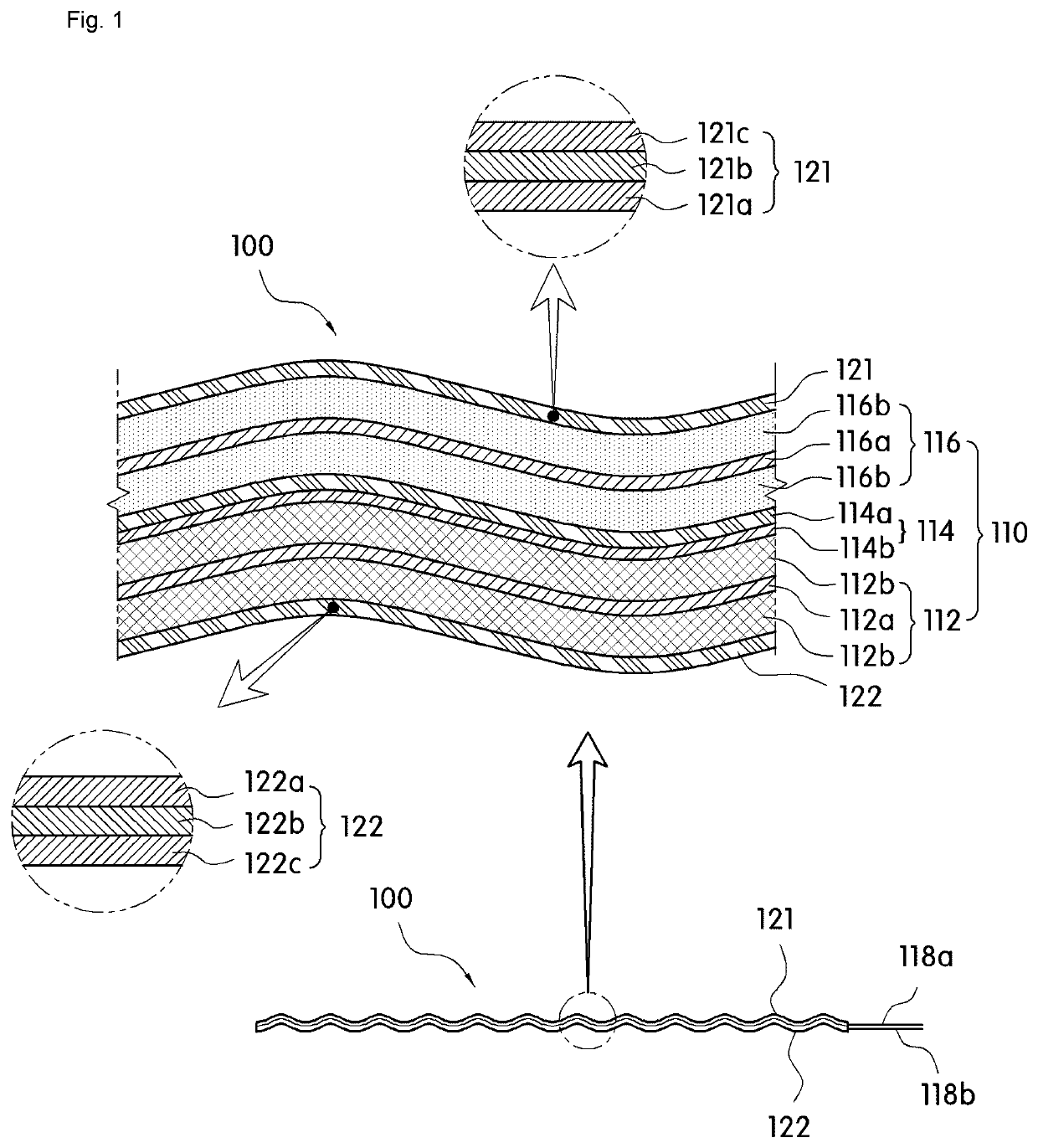
[0118]First, a metal layer formed of an aluminum material having a thickness of 30 pm was prepared, a first resin layer composed of casting polypropylene (CPP) and having a thickness of 40 μm was formed on one surface of the metal layer, and a second resin layer formed of a nylon film and having a thickness of 10 μm was formed on the other surface of the metal layer, and in this case, an exterior material having a total thickness of 85 μm was manufactured by interposing an acid-modified polypropylene layer containing 6% by weight of acrylic acid in the copolymer between the first resin layer and the metal layer by 5 μm.

[0119]Further, in order to manufacture the electrode assembly, first, a positive electrode assembly and a negative electrode assembly were prepared. The positive electrode assembly was manufacturing by casting a lithium nickel cobalt manganese (NCM)-based positive electrode active material on both surfaces of the positive electrode current collector formed of an alumi...

examples 2 to 13

[0122]In the same manner as in Example 1, a flexible battery in Tables 1 to 3 was manufactured by changing a thickness of a positive electrode current collector, a thickness and an elongation of a negative electrode current collector, and the like.

experimental example

[0123]1. Positive Electrode Durability Evaluation After Forming Pattern

[0124]A case in which no abnormality occurs in the positive electrode active material and the positive electrode current collector was shown as o, and a case in which any abnormality such as crack occurrence, interlayer peeling occurrence, or the like occurs in the positive electrode active material and the positive electrode current collector was shown as x to evaluate the positive electrode durability after forming the pattern.

[0125]2. Negative Electrode Durability Evaluation After Forming Pattern

[0126]A case in which no abnormality occurs in the negative electrode active material and the negative electrode current collector was shown as o, and a case in which any abnormality such as crack occurrence, interlayer peeling occurrence, or the like occurs in the negative electrode active material and the negative electrode current collector was shown as x to evaluate the negative electrode durability after forming t...


PUM


Abstract

A flexible battery including an electrode assembly having a positive electrode which has a positive electrode current collector having a positive electrode active material coated on a part or all of at least one surface, a negative electrode which has a foil-type negative electrode current collector having a negative electrode active material coated on a part or all of at least one surface, and a separator membrane disposed between the positive electrode and the negative electrode; an electrolyte solution; and an exterior material for sealing the electrode assembly with the electrolyte solution. Cracks are prevented from forming even when bending occurs by means of a predetermined pattern, and degradation of physical properties required for a battery can be prevented or minimized even when bending repeatedly occurs. The flexible battery can be applied to a wearable device as well as various electronic devices requiring flexibility such as a rollable display.

Description

CROSS REFERENCE TO RELATED APPLICATIONS[0001]This application is a 35 U.S.C. 371 National Phase Entry Application from PCT / KR2019 / 002646, filed Mar. 7, 2019, which claims the benefit of Korean Patent Application No. 10-2018-0027388 filed on Mar. 8, 2018 the disclosures of which are incorporated herein in their entirety by reference.TECHNICAL FIELD[0002]The present invention relates to a flexible battery, a method of manufacturing the flexible battery and an auxiliary battery including the same.BACKGROUND[0003]As consumer demands have changed due to digitization and high performance of electronic products, a market demand is also changing with development of power supplies which are thin and light in weight and have a high capacity due to high energy density.[0004]In order to meet the needs of the consumers, power supplies such as a high energy density and high capacity lithium ion secondary battery, a lithium ion polymer battery, supercapacitors (an electric double layer capacitor a...

Claims


Application Information

Patent Timeline
IPC IPC(8): H01M2/02H01M2/30H01M4/66H01M4/62H01M10/058H01M50/105
CPCH01M2/0275H01M2/30H01M4/661H01M2004/021H01M10/058H01M2220/30H01M4/623H01M4/66Y02E60/10H01M50/105Y02P70/50H01M4/13H01M10/0585H01M50/116H01M50/543
Inventor JANG, JU HEECHO, HYEON WOO
Owner AMOGREENTECH CO LTD
Why Eureka
Try Eureka