Mobile reciprocating live-saving equipment

A life-saving device and reciprocating technology, applied in life-saving equipment, building rescue and other directions, can solve the problems of wasting time in equipment recycling, increasing hazards, reducing life-saving efficiency, etc. Effect

Inactive Publication Date: 2008-10-29
四川宁江精密工业有限责任公司
View PDF0 Cites 6 Cited by
  • Summary
  • Abstract
  • Description
  • Claims
  • Application Information

AI Technical Summary

Problems solved by technology

[0002] At present, in order to alleviate the shortage of land resources, buildings are becoming more and more high-altitude, and asking for houses in the sky will be the trend of human urban construction in the future. The increase in high-rise buildings has greatly increased the hazards caused by high-rise disasters. The main reason is that high-rise life-saving equipment Without popularization, when a disaster occurs, it is difficult for rescuers to rescue people trapped in high-rise buildings in time
[0003] The main shortcoming that existing group escape equipment exists is: 1) existing lifesaving equipment needs power to drive, and when disaster takes place, the probability of power supply being cut off is very high, in this case using lifesaving device itself just has danger ; 2) most of the existing life-saving equipment adopts the principle of mechanical friction to realize slow-down life-saving, and its structural design cannot guarantee safe use; The development of life-saving work in emergencies; 4) the existing life-saving equipment is a single life-saving, unable to achieve reciprocating uninterrupted life-saving, the recovery of equipment is a waste of time, greatly reducing the efficiency of life-saving; 6) most of the group life-saving equipment is It is fixedly installed on the roof or on a specific rescue floor, and cannot be used flexibly

Method used


Image

  • Mobile reciprocating live-saving equipment
  • Mobile reciprocating live-saving equipment
  • Mobile reciprocating live-saving equipment

Examples


Embodiment Construction

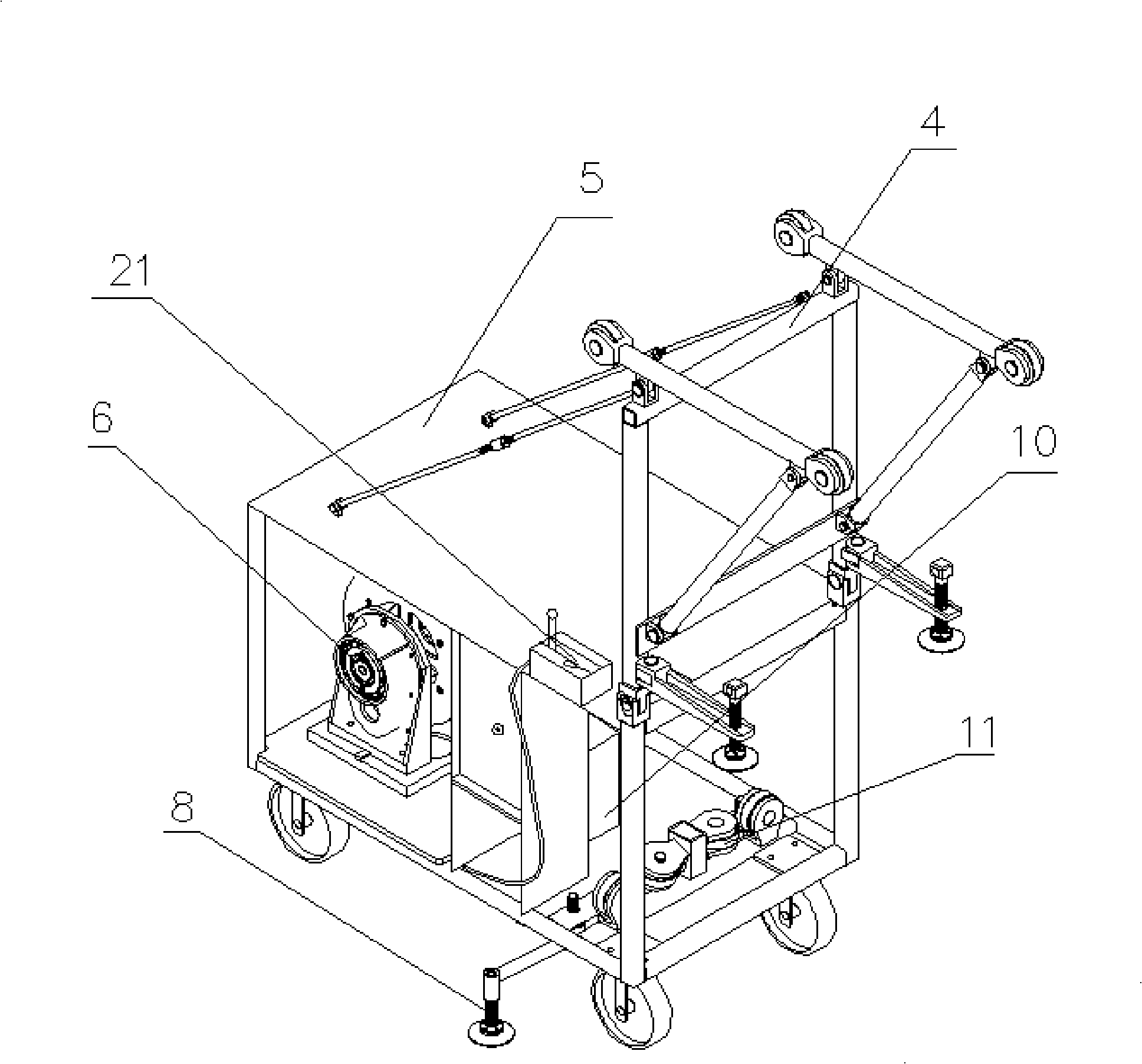
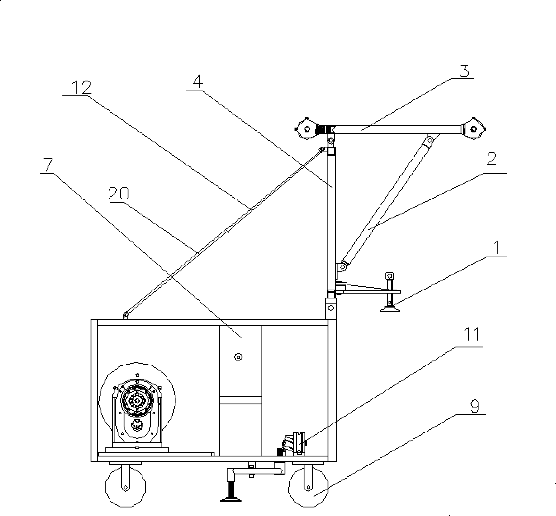
[0012] Such as figure 1 , figure 2 As shown, the present invention includes a vehicle body 5 , and a damper 6 , an adjustable electric energy receiving and converting device 10 and an electric control cabinet 7 are installed inside the vehicle body 5 .

[0013] Wheel 9 is installed below car body 5, and wheel 9 is made up of two straight wheels and two universal wheels.

[0014] In order to alleviate the impact of the present invention when running at maximum load, a set of foldable adjustable support frame is installed on the car body 5. 1, the supporting body 4 is installed on the car body 5 through a hinge, two outstretching arms 3, two oblique supporting arms 2 and two supporting platforms 1 are installed on the supporting body 4 through a hinge, wherein the supporting body 4, the extending The arm 3 and the oblique support arm 2 form a triangular support. In order to increase the stability of the adjustable support frame, an upper tie rod 12 and a lower rod 20 are als...


PUM


Abstract

The invention provides a reciprocating type lifesaving apparatus that can be used movably, which comprises a bodywork and a rope; a damping machine, an adjustable electric energy receiving and reforming unit and an electrical cabinet are arranged in the bodywork; the adjustable electric energy receiving and reforming unit is connected with a speed governing knob at the electrical cabinet; the damping machine is connected with the adjustable electric energy receiving and reforming unit; the damping machine consists of a stator, a rotor and a rope roll; the rope roll is connected with the rotor by the rope. The apparatus of the invention is equipped with a wheel, so to the apparatus can move flexibly and conveniently, and can be pushed rapidly to a suitable position to use in an emergency; different falling speeds of the invention can be selected according to different crowds and the number of the escaping people, thereby reducing a mental pressure of the escaping people in the emergency and helping the people to escape from a danger zone safely; the apparatus of the invention can also be hovered arbitrarily when in use, so as to help the escaping people on different floors to escape successfully.

Description

technical field [0001] The invention relates to a high-rise life-saving device, in particular to a reciprocating life-saving device that can be moved when a high-rise disaster occurs. Background technique [0002] At present, in order to alleviate the shortage of land resources, buildings are becoming more and more high-altitude, and asking for houses in the sky will be the trend of human urban construction in the future. The increase in high-rise buildings has greatly increased the hazards caused by high-rise disasters. The main reason is that high-rise life-saving equipment Without popularization, when a disaster occurs, it is difficult for rescuers to rescue people trapped in high-rise buildings in time. [0003] The main shortcoming that existing group escape equipment exists is: 1) existing lifesaving equipment needs power to drive, and when disaster takes place, the probability of power supply being cut off is very high, in this case using lifesaving device itself just...

Claims


Application Information

Patent Timeline
Patent Type & Authority Applications(China)
IPC IPC(8): A62B1/10A62B1/18
Inventor 谭伟峰曹从波
Owner 四川宁江精密工业有限责任公司
Why Eureka
Try Eureka