Backlight module and optical film immobilizing method

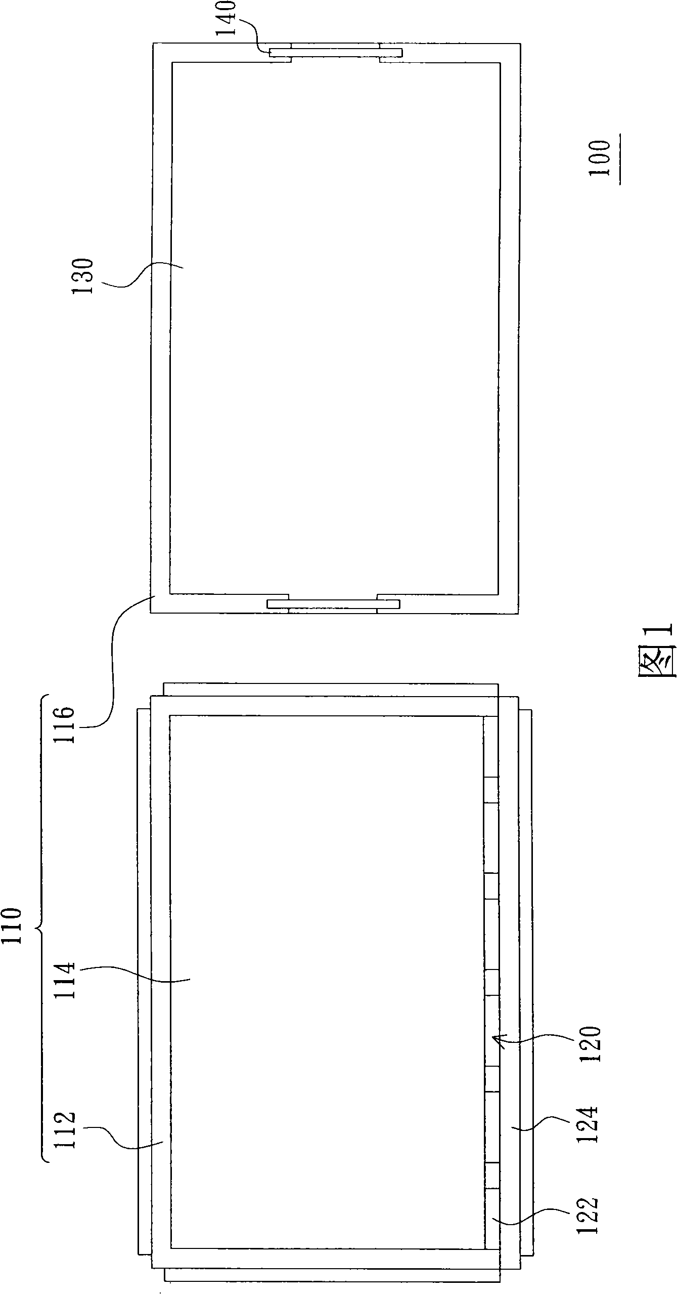
A technology of backlight module and optical film, which is applied in optics, nonlinear optics, components of lighting devices, etc., and can solve the problems of cumbersome assembly process, high assembly man-hours and assembly costs of backlight module 100, and many assembly components.

Active Publication Date: 2008-11-19
AU OPTRONICS CORP
View PDF0 Cites 15 Cited by
  • Summary
  • Abstract
  • Description
  • Claims
  • Application Information

AI Technical Summary

Problems solved by technology

[0004] The optical film 130 of the conventional backlight module 100 is fixed on the frame body 116 by means of two adhesive tapes 140, so the assembly process of the existing backlight module 100 is relatively cumbersome and has many assembly components.
Therefore, the assembly man-hours and assembly costs of the existing backlight module 100 are relatively high.

Method used


Image

  • Backlight module and optical film immobilizing method
  • Backlight module and optical film immobilizing method
  • Backlight module and optical film immobilizing method

Examples


no. 1 example

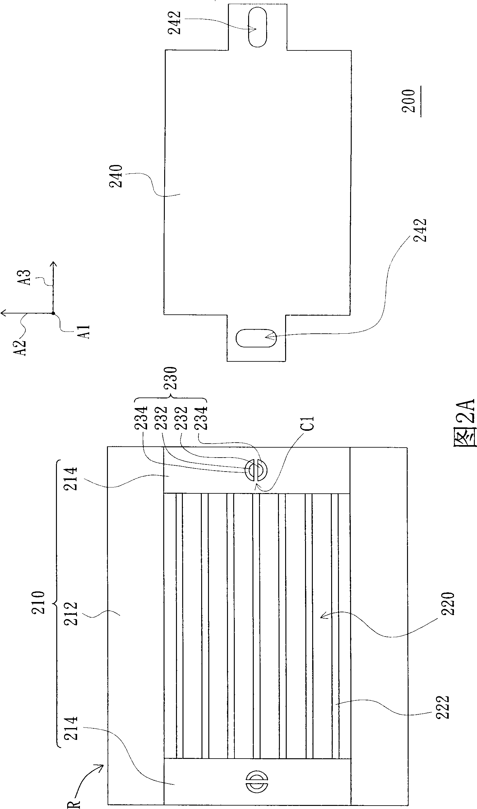
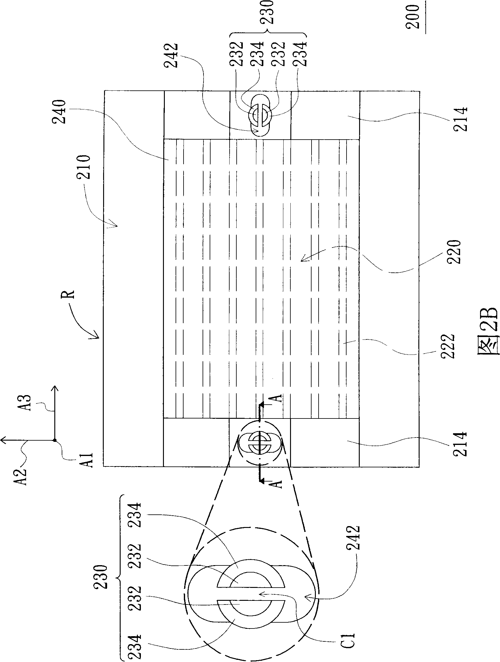
[0050] FIG. 2A is a partially exploded schematic diagram of a backlight module according to the first embodiment of the present invention, and FIG. 2B is a schematic diagram of the combination of the backlight module in FIG. 2A , Figure 2C A schematic cross-sectional view of the backlight module in FIG. 2B along the line A-A is shown. Please refer to Figure 2A, Figure 2B and Figure 2C , the backlight module 200 of this embodiment includes a base 210 , a light source 220 , a plurality of fixing components 230 and at least one optical film 240 . The light source 220 is disposed on the base 210 and is suitable for emitting light. In this embodiment, the light source 220 includes a plurality of lamp tubes 222 arranged in parallel, and the base 210 and the fixing components 230 form a carrier R.

[0051] The base 210 of this embodiment includes a base 212 and two lamp clamping parts 214 . The light tube holders 214 are disposed on opposite sides of the base 212 to hold each ligh...

no. 2 example

[0059] FIG. 4A is a schematic diagram of a combination of a backlight module according to the second embodiment of the present invention, Figure 4B A schematic cross-sectional view of the backlight module of FIG. 4A along the line B-B is shown, Figure 4C A schematic cross-sectional view of the backlight module shown in FIG. 4A along line C-C is shown. Please refer to Figure 4A, Figure 4B and Figure 4C , the difference between the backlight module 300 of this embodiment and the backlight module 200 of the first embodiment is that, Figure 3A The appearance of the fixing assembly 330 on the left in FIG. 2 is different from that of the fixing assembly 230 on the left in FIG. 2 .

[0060] Each flexible connection part 332 of the fixing component 330 on the left in FIG. 4A has at least one pair of flexible connection parts 332 a (only one pair is schematically shown in FIG. 4A ), which is connected to the base 310 . Each buckle 334 of the left fixing component 330 in FIG. 4...

no. 3 example

[0063] FIG. 5 is a partially exploded schematic diagram of a backlight module according to a third embodiment of the present invention. Please refer to FIG. 5 , the base 410 of the backlight module 400 of this embodiment includes a base 412 , a light guide plate 414 and a frame 416 disposed on the base 412 . The light guide plate 414 is disposed on the base 412 , and the light source 420 includes a plurality of LED devices 422 and a circuit board 424 . The LED devices 422 are electrically connected to the circuit board 424 , and the light source 420 is disposed on the base 412 and located beside the light guide plate 414 . The flexible connectors 432 of each fixing component 430 are disposed on the frame body 416 . After the backlight module 400 is assembled (not shown), the frame body 416 is disposed on the base 412 , and the optical film 440 covers the light guide plate 414 .

[0064] In summary, the embodiments of the present invention have at least the following or other...


PUM


Abstract

The invention discloses a fixing method for a backlight module and an optical patch; the backlight module comprises a base, a light source, a plurality of fixed components and an optical patch. The light source is arranged on the base and can emit light. Each fixed component has a pair of flexible connectors arranged on the base and a pair of clipping fasteners which are respectively arranged on the flexible connectors. The flexible connectors of each fixed component maintain the gaps, and the flexible connectors of each fixed component can make flexible deformation by narrowing the gaps. The optical patch is arranged on the base and has a plurality of fixed holes. The light passes through the optical patch. The flexible connectors of each fixed component pass through one of the fixed holes; each fixed hole is limited between each clipping fastener of the corresponding fixed component and the base, so that the optical patch is restricted in moving on a first axis, a second axis and a third axis; the first axis, the second axis and the third axis are perpendicular to each other.

Description

technical field [0001] The present invention relates to a fixing method of a backlight module (backlight module) and an optical film (optical film), and in particular relates to a backlight module with a fixing module (fixing module) and using the fixing module to fix the optical film fixed method. Background technique [0002] FIG. 1 is a partially exploded schematic view of a conventional backlight module. The conventional backlight module 100 includes a base 110 , a light source 120 and an optical film 130 . The light source 120 includes a plurality of light-emitting diode devices (LED devices) 122 and a circuit board 124 . And the LED devices 122 are electrically connected to the circuit board 124 . [0003] The base 110 includes a back bezel 112 , a light-guiding plate (LGP) 114 and a frame 116 disposed on the base 112 . The light guide plate 114 is disposed on the base 112 , and the light source 120 is disposed on the base 112 and located beside the light guide pla...

Claims


Application Information

Patent Timeline
Patent Type & Authority Applications(China)
IPC IPC(8): G02F1/13357G02F1/1333F21V21/00G02F1/1335
Inventor 张加欣陈秋君
Owner AU OPTRONICS CORP
Why Eureka
Try Eureka