Clapping tunable electromagnetic release

An electromagnetic release and snap-fit ​​technology, which is applied in the direction of protection switch operation/release mechanism, etc., can solve the problems of limited adjustment ability, inability to play a protective role, insensitive tripping of electromagnetic release, etc., to achieve sensitive tripping. Effect

Active Publication Date: 2008-11-19
CHANGSHU SWITCHGEAR MFG CO LTD (FORMER CHANGSHU SWITCHGEAR PLANT)
View PDF0 Cites 2 Cited by
  • Summary
  • Abstract
  • Description
  • Claims
  • Application Information

AI Technical Summary

Problems solved by technology

However, when the above structure is used for small current setting, for example, the frame level of the circuit breaker is 250A, and the current adjustment range is required to be below 200A, according to the relation F ∞ ( I · N ) 2 S δ 2 , Due to the above structure, the number of turns N, the magnetically permeable air gap δ, and the area S of the magnetically permeable air gap remain unchanged. At this time, the current is small, and the attraction force provided by the iron core 5 is also small, so the iron core 5 is not easy to be attracted. , Therefore, the tripping of the electromagnetic tripper is not sensitive, the tripping is not reliable, and it cannot play a protective role.
That is to say, the adjustment range of the current in a frame is limited. Taking the above-mentioned circuit breaker frame level of 250A as an example, the current setting range is only 200-250A, so the adjustment ability is limited.

Method used


Image

  • Clapping tunable electromagnetic release
  • Clapping tunable electromagnetic release
  • Clapping tunable electromagnetic release

Examples


Embodiment Construction

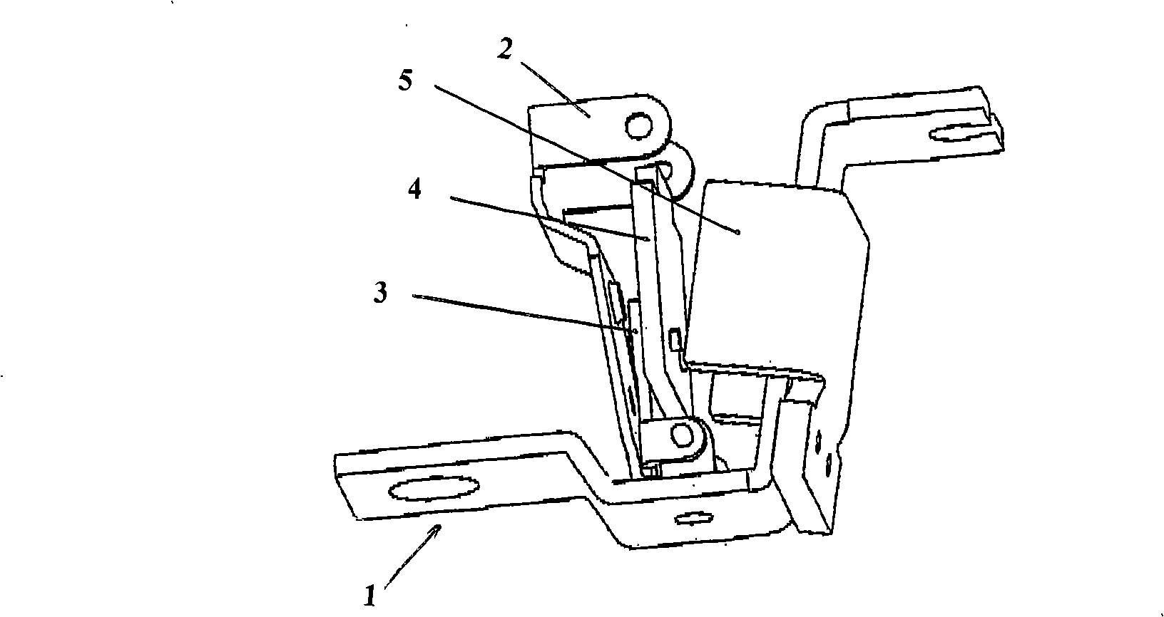
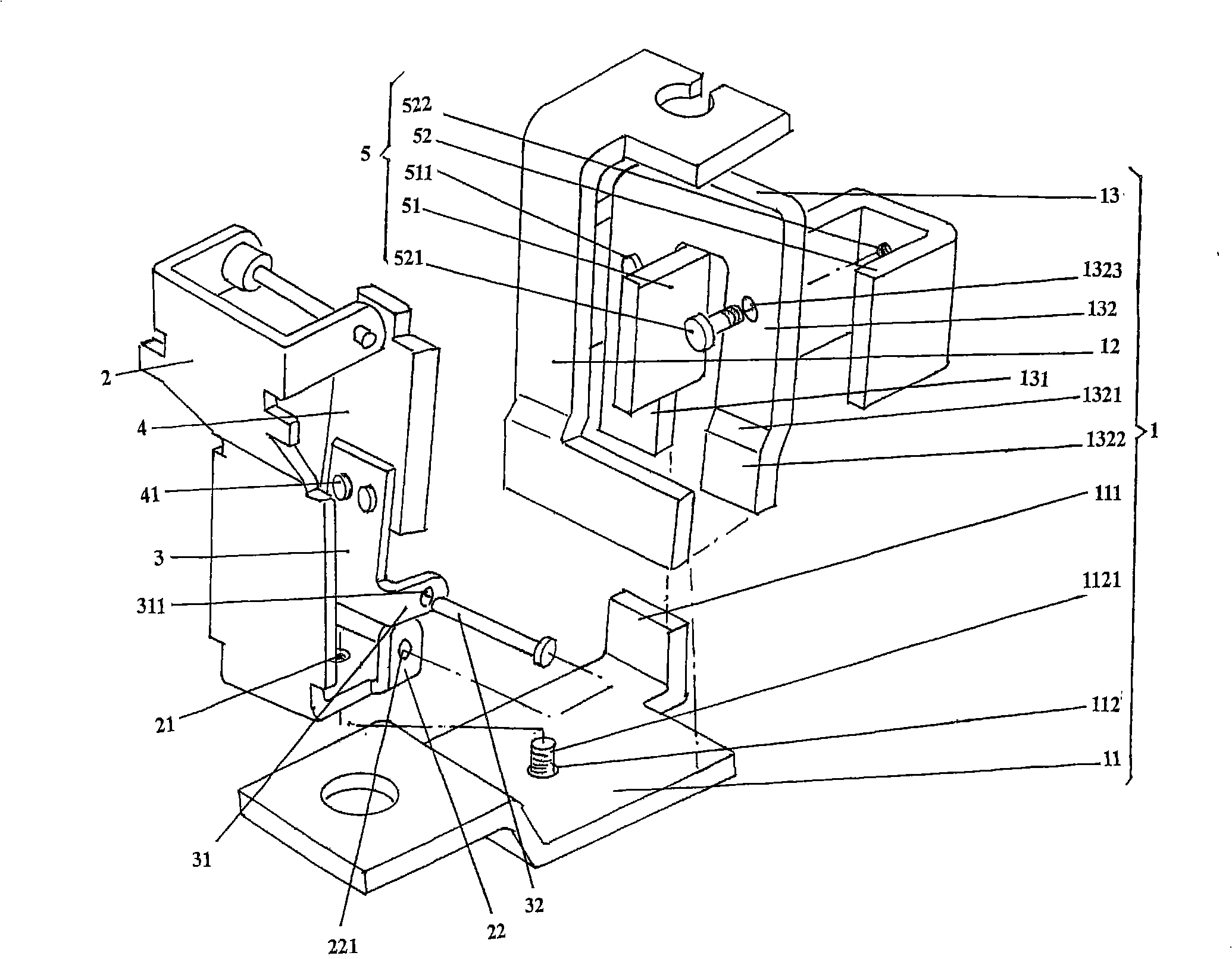
[0015] please see figure 2 , the current-carrying wire 1 composed of the first, second, and third conductive rods 11, 12, 13 is given. Taking the current position shown in the figure as an example, a first screw is provided in the near middle of the first conductive rod 11 hole 112, and the right end of the first conductive rod 11 is processed with a first bent portion 111 on one side, and the first bent portion 111 and the first conductive rod 11 preferably form a right angle relationship of 90°. The lower end of the second conductive rod 12 is welded with the second arm 132 by preferably welding with the second arm 132 at the position corresponding to the lower end of the second arm 132 of the third conductive rod 13, that is, the welding plane 1322 of the second arm 132, so that The second and third conductive rods 12 and 13 are integrated, and the lower end of the first arm 131 of the third conductive rod 13 is welded to the first bending portion 111, so that the first, s...


PUM


Abstract

Disclosed is an adjustable clapper electromagnetic release, belonging to the breaker technical field. The adjustable clapper electromagnetic release comprises a current-carrying wire, a first bracket fixed on the current-carrying wire, a second bracket which is hinged on the first bracket, an armature iron fixed on the second bracket and an iron core which is fixed on the current-carrying wire and corresponds with the armature iron. The iron core comprises a first U-shaped core body and a second U-shaped core body, which are fixed with the current-carrying wire. The adjustable clapper electromagnetic release has the advantages that the adjustable clapper electromagnetic release adopts the first U-shaped core body and the second U-shaped core body which develop into two separate magnetic loops with the armature iron; in this way, the first U-shaped core body and the second U-shaped core body develop four magnetic air gaps Delta with the armature iron, thus enlarging the magnetic area S; meanwhile, the number of the ampere-turns that running through the first U-shaped core body is larger, so even when small current runs through the current-carrying wire, large magnetic force will be generated, thus ensuring sensitive and reliable release; the current adjustment range can be enlarged from 200-250A in the prior art to 125-250A.

Description

technical field [0001] The invention belongs to the technical field of circuit breakers, and in particular relates to a snap-fit ​​adjustable electromagnetic tripper installed in a low-voltage molded case circuit breaker. Background technique [0002] The structure of the clapping type adjustable electromagnetic tripper widely used in the prior art consists of figure 1 As shown, it includes a current-carrying wire 1, first and second brackets 2, 3, an armature 4 and an iron core 5, the first bracket 2 is fixed on the current-carrying wire 1, the second bracket 3 is hinged with the first bracket 2, and the armature 4 is fixed to the second bracket 3 , and the iron core 5 is fixed to the current-carrying wire 1 and corresponds to the armature 4 . The snap-fit ​​adjustable electromagnetic release of this structure can be applied to large current setting and adjustment. For example, the frame level of the circuit breaker is 250A, and its current adjustment range is 200-250A, be...

Claims


Application Information

Patent Timeline
Patent Type & Authority Applications(China)
IPC IPC(8): H01H71/24
Inventor 唐维春吴海霞陈志刚王炯华管瑞良
Owner CHANGSHU SWITCHGEAR MFG CO LTD (FORMER CHANGSHU SWITCHGEAR PLANT)
Why Eureka
Try Eureka