
Electricity-controlled lock

A technology of electronically controlled locks and main bolts, which is applied in the field of electronically controlled locks. It can solve the problems of lack of electric control, few lock points, and large wear and tear of locks, and achieve the effects of good anti-theft performance, convenient operation, and low strength.

Inactive Publication Date: 2008-12-03
刘恩
View PDF0 Cites 23 Cited by
  • Summary
  • Abstract
  • Description
  • Claims
  • Application Information

AI Technical Summary

Problems solved by technology

[0002] At present, all kinds of locks sold on the market, especially the locks on anti-theft doors, are locked or unlocked by inserting a key into the lock and turning it a few times when opening and closing the door. , and the wear and tear on the lock is relatively large, the life of the lock is not long, it is inconvenient to use, and it does not have the function of electric control, and it is completely opened and closed by manual energy. The function of multi-directional automatic locking cannot be realized. After electric unlocking, it is necessary to rely on the manual outside handle to complete the unlocking and recover the deadbolt. It is difficult to achieve multi-directional locking, resulting in low anti-theft performance

Method used


Image

  • Electricity-controlled lock
  • Electricity-controlled lock
  • Electricity-controlled lock

Examples


Embodiment Construction

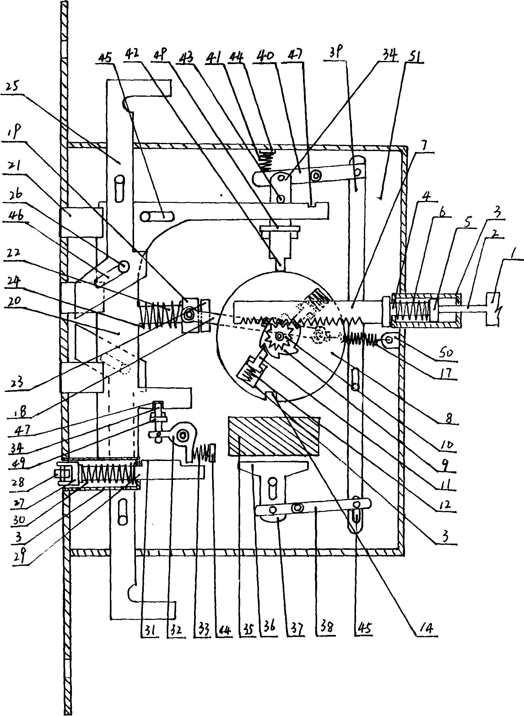
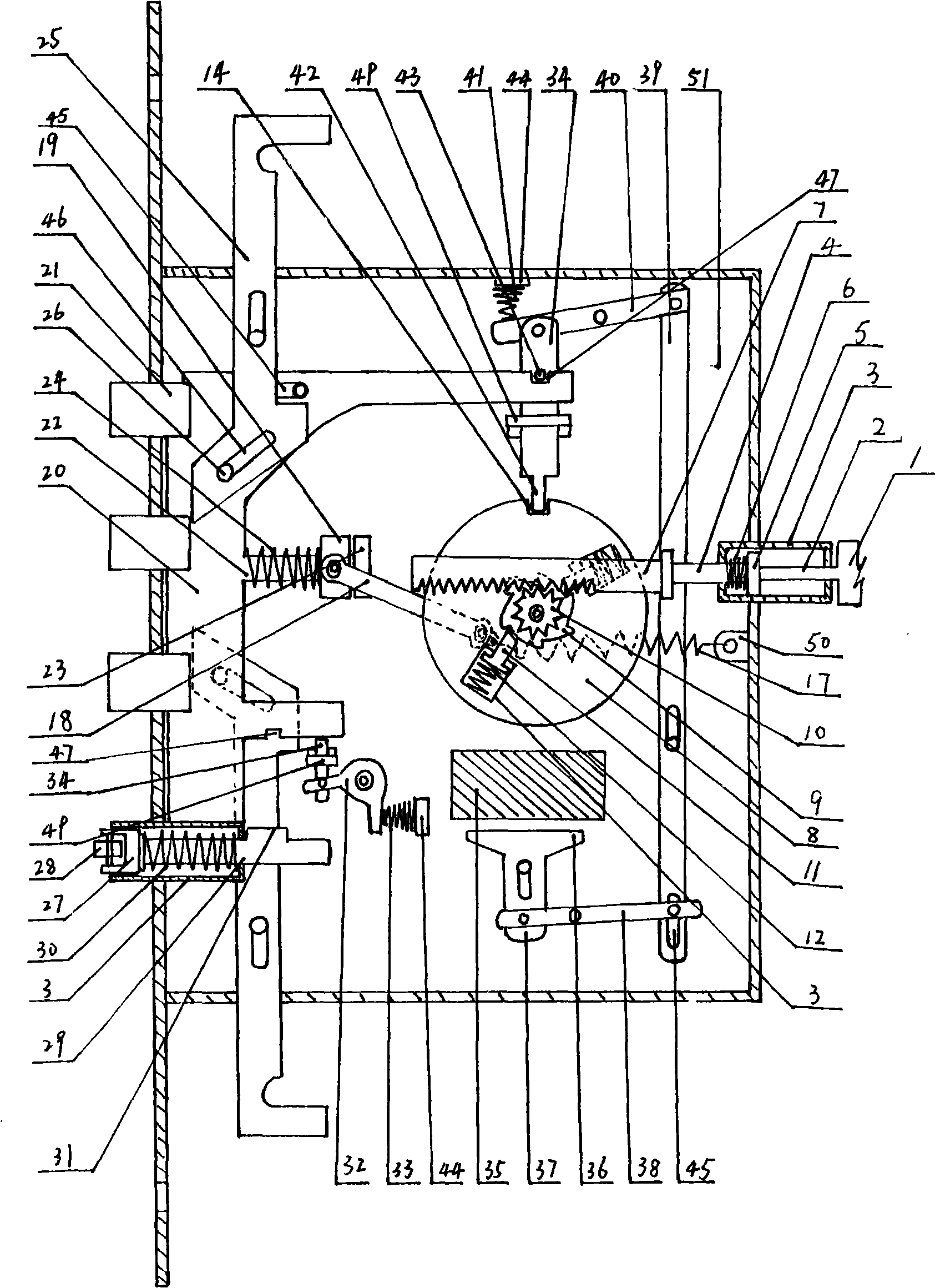
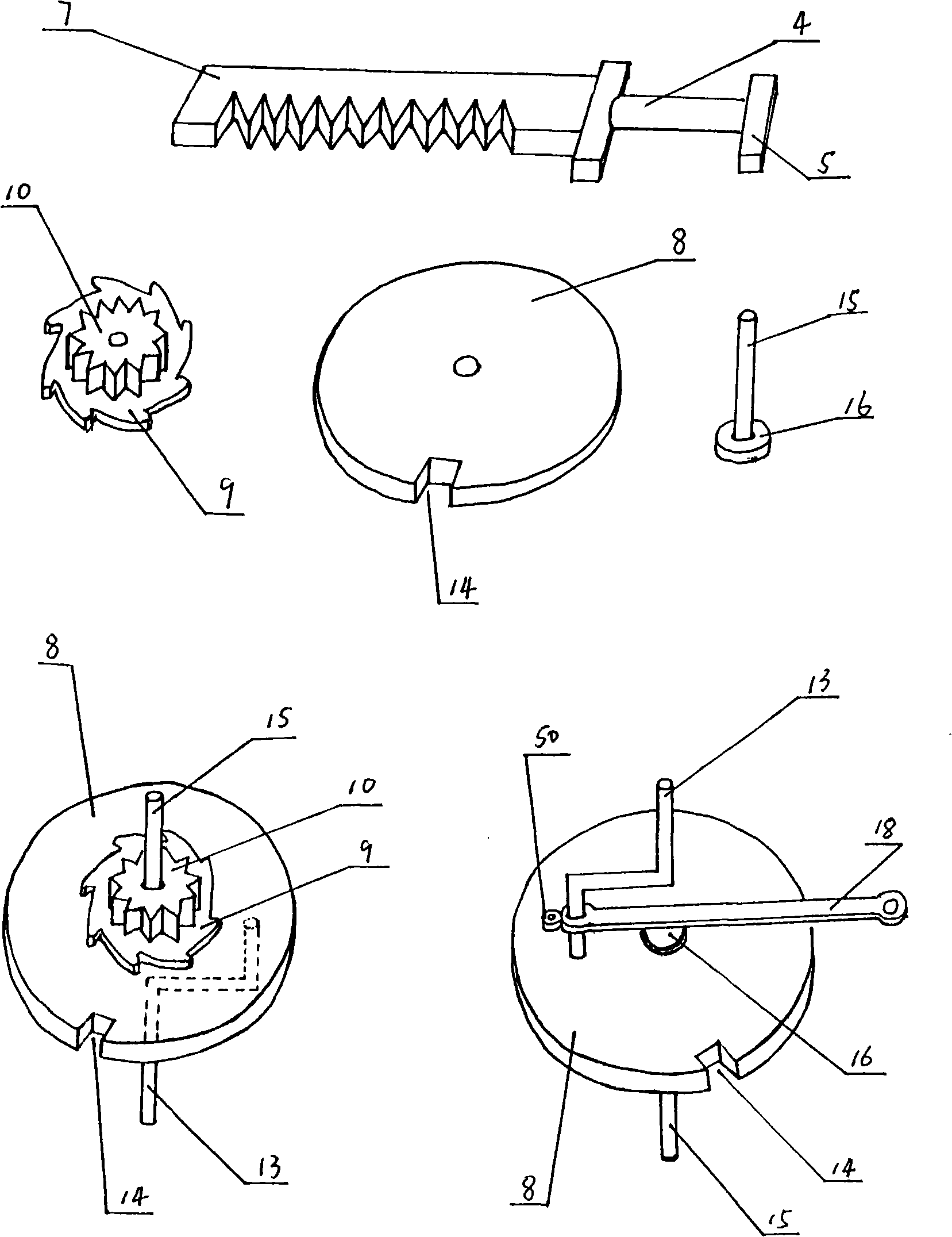
[0013] Such as figure 1 , figure 2 , image 3 , Figure 4 , Figure 5As shown, a slidable drive rod (1) is provided in the door leaf (54), and the drive rod (1) is provided with a step (31), and one end thereof stretches out from the door leaf (54) and pushes against the door frame ( 53), the transmission head (2) on the other end stretches into the guide tube (3) and touches the bar boss (5) on the feeler bar (4) in the guide tube (3), and the feeler bar (4) The contact rod return spring (6) is arranged on the top, the contact rod (4) is fixedly arranged with the rack (7), and the rack (7) is arranged outside the guide tube (3) and is connected with the one-way ratchet on the energy storage flywheel (8) ( 9) The active pinion gear (10) formed at the center position on the surface is meshed and driven, and the surface of the energy storage flywheel (8) is provided with a plurality of one-way ratchets (11) corresponding to the one-way ratchet (9). One end of the claw (11)...


PUM


Abstract

The invention relates to an electric control lock, which comprises a flywheel stored energy transmission mechanism, a latch bolt instantaneous locking mechanism and an electric driving mechanism. The flywheel stored energy transmission mechanism is composed of a rack, a driving pinion, a one-way ratchet wheel, a flywheel, a one-way pawl, a compression spring, a rotating shaft, an eccentric crankshaft and a groove; the latch bolt instantaneous locking mechanism is composed of a latch bolt, a roller, a latch bolt bar, a resetting spring of the latch bolt bar, a step, a bayonet lock plate, a shifting fork block and a resetting spring of the shifting fork block; and the electric driving mechanism is composed of an electromagnet, an armature iron, a pulling plate of the armature iron, a connecting rod, a pull rod, an unlocking connecting rod key, a bayonet lock plate and a resetting spring of the unlocking connecting rod key. The electric control lock is characterized in that a main lock tongue body and all lock tongues on a universal hauling piece, as well as a guide pipe fixed on the main lock tongue body, can be fully and automatically inserted into the door frame during the process of closing the door, and can be automatically retracted during the process of opening the door; the force of the electric opening mechanism is small; multi-dimensional locking and unlocking can be fully achieved; the anti-theft performance is good; the operation is convenient; and the electric control lock facilitates all the intelligent controllers to be used in a matching manner, such as electric control magnetic cards, remote controllers and fingerprints, etc.

Description

Technical field: [0001] The invention relates to a door lock of a lockset, in particular to an electric control lock used for doors and cabinets. Background technique: [0002] At present, all kinds of locks sold on the market, especially the locks on anti-theft doors, are locked or unlocked by inserting a key into the lock and turning it a few times when opening and closing the door. , and the wear and tear on the lock is relatively large, the life of the lock is not long, it is inconvenient to use, and it does not have the function of electric control, and it is completely opened and closed by manual energy. The function of multi-directional automatic locking cannot be completed. After electric unlocking, it is necessary to rely on the manual outside handle to complete the unlocking and recover the deadbolt. It is difficult to achieve multi-directional lock locking, resulting in low anti-theft performance. Invention content: [0003] The purpose of the present invention...

Claims


Application Information

Patent Timeline
IPC IPC(8): E05B47/02
Inventor 刘恩
Owner 刘恩
Learn More