

Zoom lens system, optical apparatus, and method for forming an image
A zoom lens and lens group technology, applied in the field of zoom lens system, can solve the problems of low zoom ratio, can not fully meet the needs of high zoom ratio, etc., and achieve the effect of high zoom ratio and high optical performance
- Summary
- Abstract
- Description
- Claims
- Application Information
AI Technical Summary
Problems solved by technology
Method used
Image

Examples
example 1
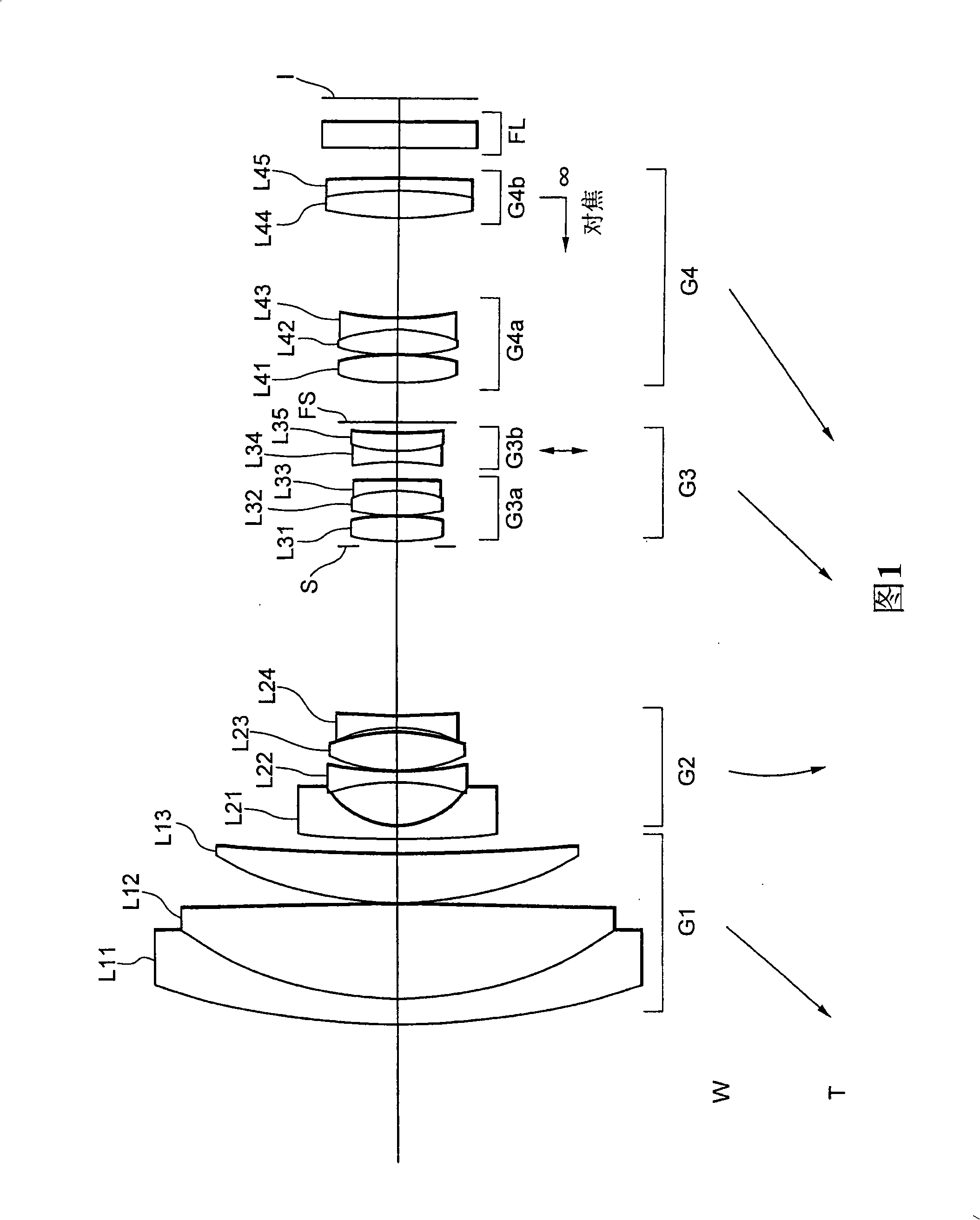
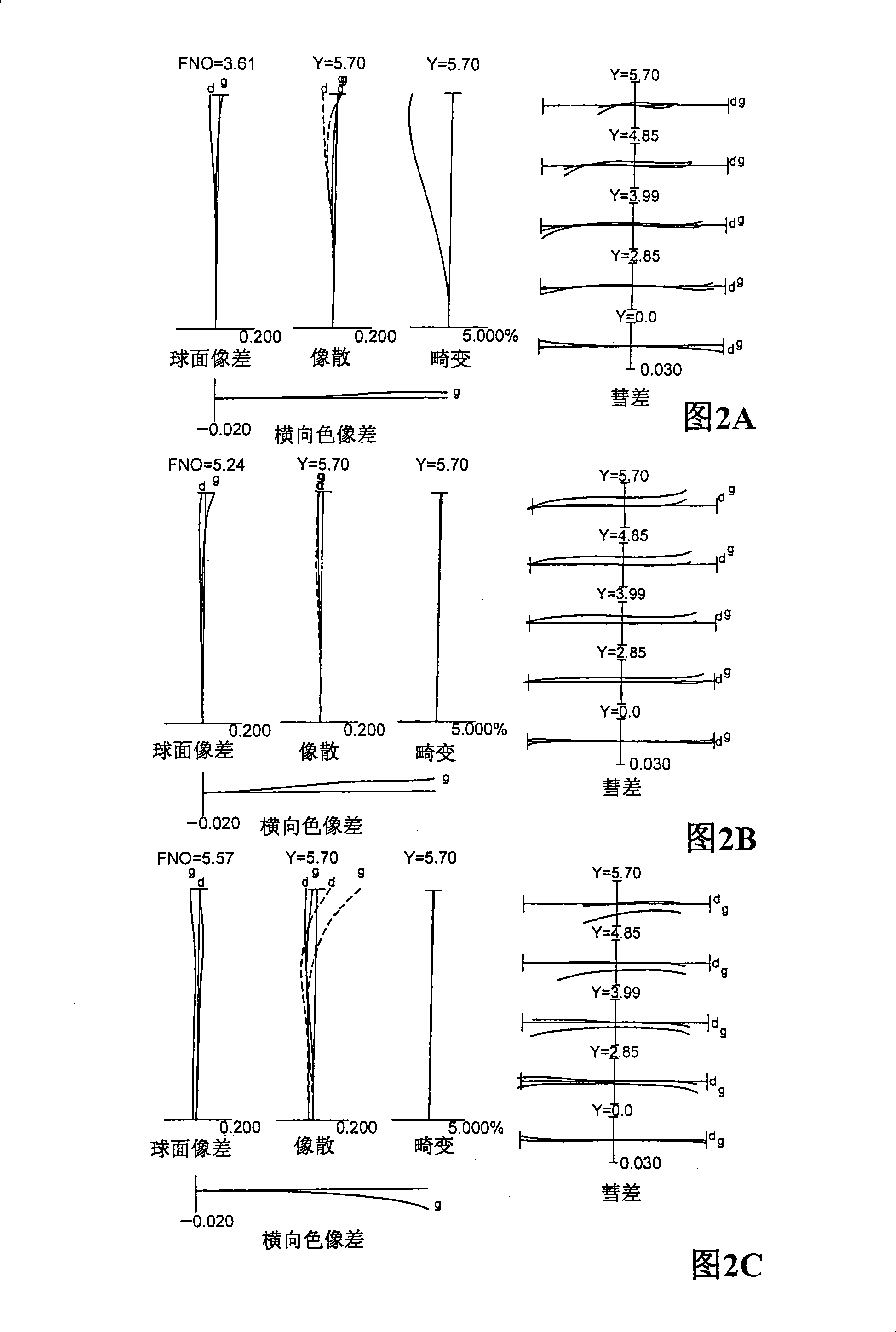
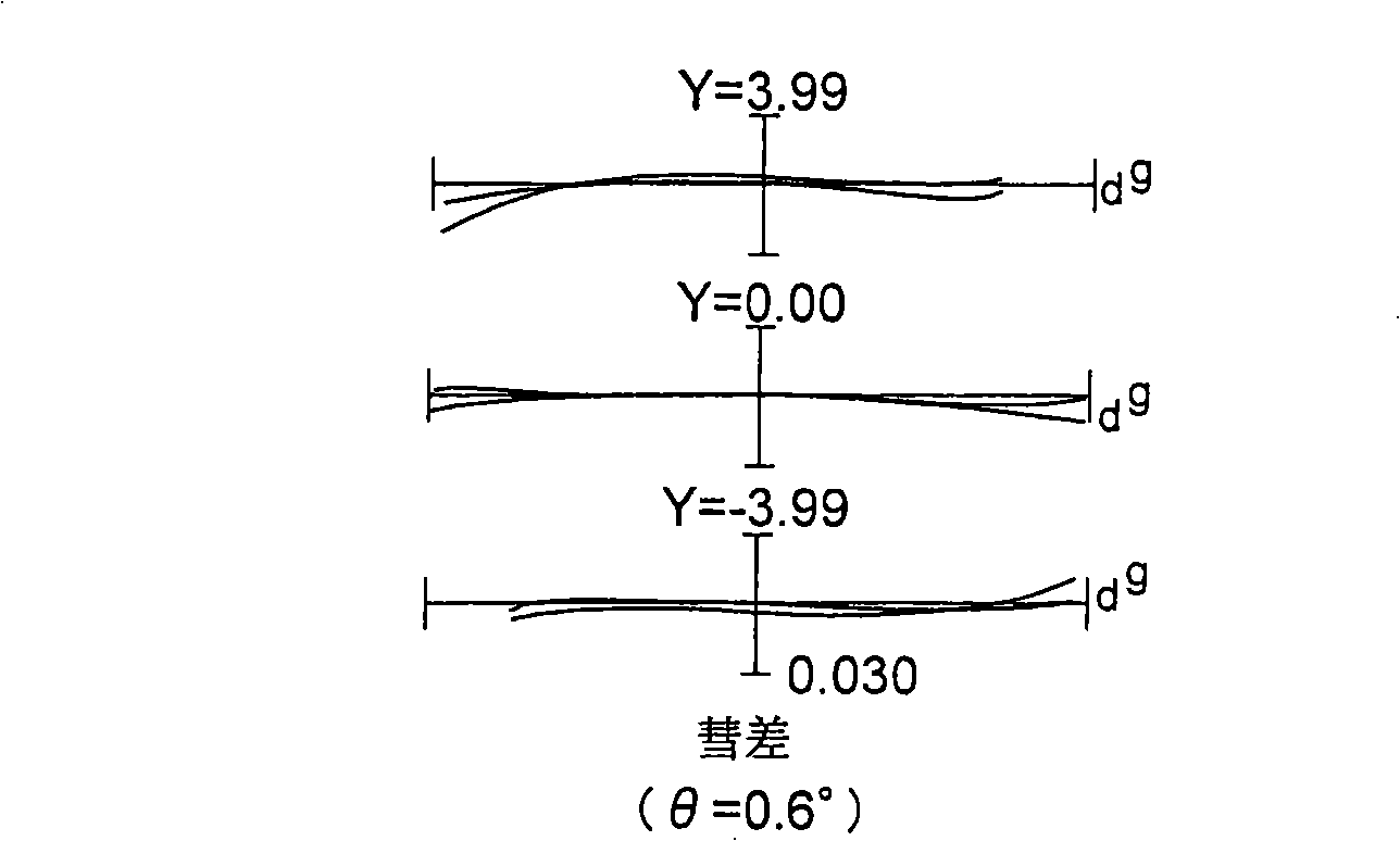
[0094] FIG. 1 is a sectional view showing a lens layout of a zoom lens system according to Example 1 together with a zoom locus of each lens group.
[0095] The zoom lens system according to Example 1 is composed of, in order from the object along the optical axis: a first lens group G1′ having positive refractive power; a second lens group G2′ having negative refractive power; a third lens group G3 having positive refractive power; and a fourth lens group having positive refractive power disposed on the most image plane I side.
[0096] When zooming from the wide-angle end state W to the telephoto end state T, the first lens group G1, the third lens group G3, and the fourth lens group G4 move toward the object, and the second lens group G2 moves so that the first lens group The distance between G1 and the second lens group G2 increases, the distance between the second lens group G2 and the third lens group G3 decreases, and the distance between the third lens group G3 and the...
example 2
[0206] 4 is a sectional view showing a lens layout of a zoom lens system according to Example 2 together with a zoom locus of each lens group.
[0207] The zoom lens system according to Example 2 is composed of the following parts in order from the object along the optical axis: the first lens group G1 having positive refractive power, the second lens group G2 having negative refractive power, the second lens group G2 having positive refractive power, The third lens group G3 with refractive power, and the fourth lens group with positive refractive power disposed on the most image plane I side.
[0208] When zooming from the wide-angle end state W to the telephoto end state T, the first lens group G1, the third lens group G3, and the fourth lens group G4 move toward the object, and the second lens group G2 moves so that the first lens group The distance between G1 and the second lens group G2 increases, the distance between the second lens group G2 and the third lens group G3 d...
example 3
[0307] 7 is a sectional view showing a lens layout of a zoom lens system according to Example 3 together with a zoom locus of each lens group.
[0308] The zoom lens system according to Example 3 is composed of the following parts in order from the object along the optical axis: the first lens group G1 having positive refractive power, the second lens group G2 having negative refractive power, the second lens group G2 having positive refractive power, The third lens group G3 with refractive power, and the fourth lens group with positive refractive power disposed on the most image plane I side.
[0309] When zooming from the wide-angle end state W to the telephoto end state T, the first lens group G1, the third lens group G3, and the fourth lens group G4 move toward the object, and the second lens group G2 moves so that the first lens group The distance between G1 and the second lens group G2 increases, the distance between the second lens group G2 and the third lens group G3 d...
PUM
 Abstract
Description
Claims
Application Information