
Valve actuating mechanism for internal-combustion engine capable of automatic phase conversion

A technology of valve train and internal combustion engine, applied in the direction of engine components, machines/engines, mechanical equipment, etc., can solve the problems of complex structure and cannot change the valve phase, etc., and achieve the effect of increasing or decreasing the exhaust phase.

Inactive Publication Date: 2008-12-10
詹炳岳
View PDF0 Cites 4 Cited by
  • Summary
  • Abstract
  • Description
  • Claims
  • Application Information

AI Technical Summary

Problems solved by technology

[0003] The present invention provides an automatic phase-changing internal combustion engine gas distribution mechanism, the main purpose of which is to overcome the above-mentioned existing valve timing and valve lift control mechanism which only has two states of low-speed working condition and high-speed working condition, and the variable distribution mechanism for adjusting the camshaft rotation angle. The gas timing system can only change the gas distribution timing but not the gas distribution phase. At the same time, the structures of both are relatively complicated, etc.

Method used


Image

  • Valve actuating mechanism for internal-combustion engine capable of automatic phase conversion
  • Valve actuating mechanism for internal-combustion engine capable of automatic phase conversion
  • Valve actuating mechanism for internal-combustion engine capable of automatic phase conversion

Examples


Embodiment Construction

[0022] Specific embodiments of the present invention will be described below with reference to the accompanying drawings.

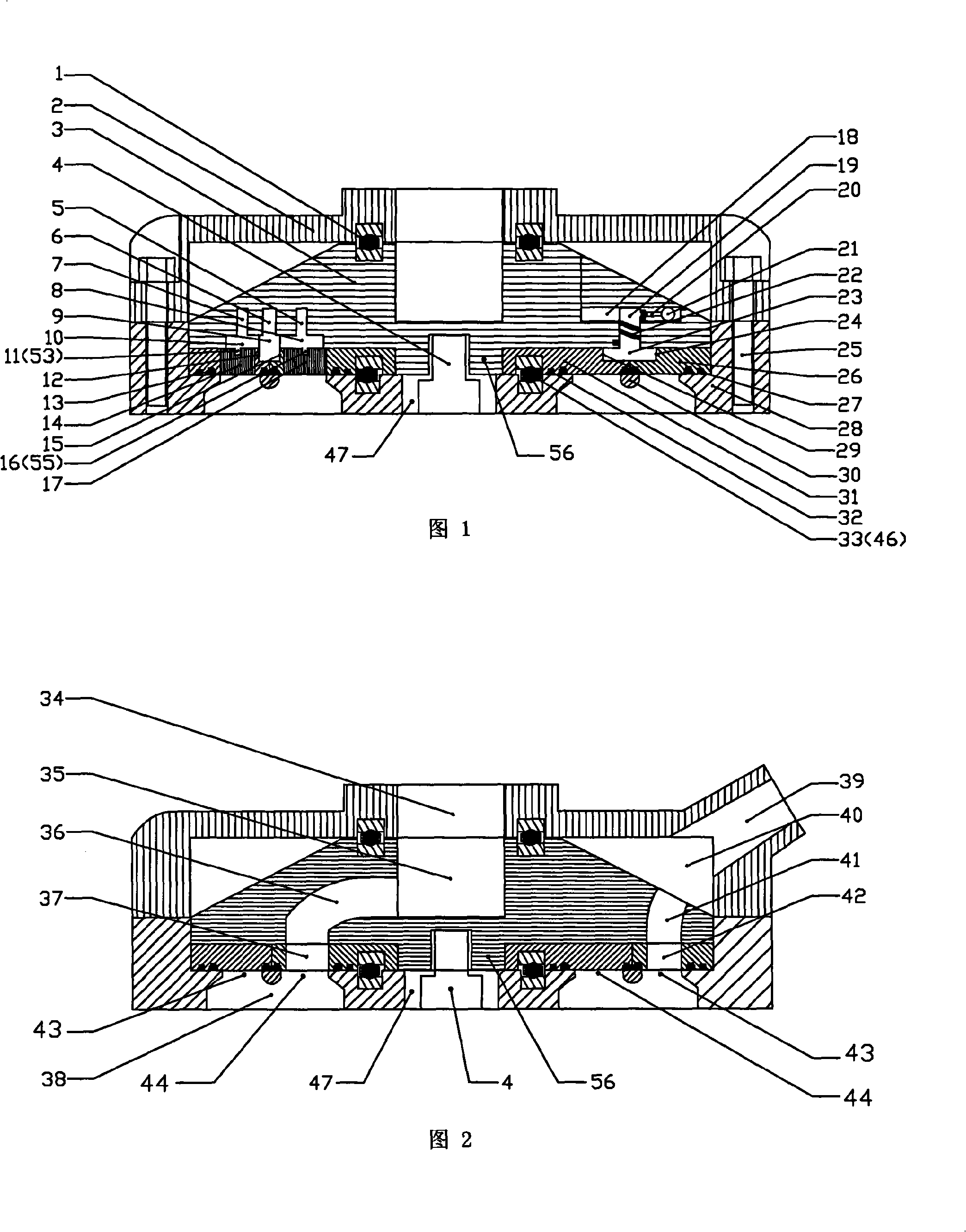
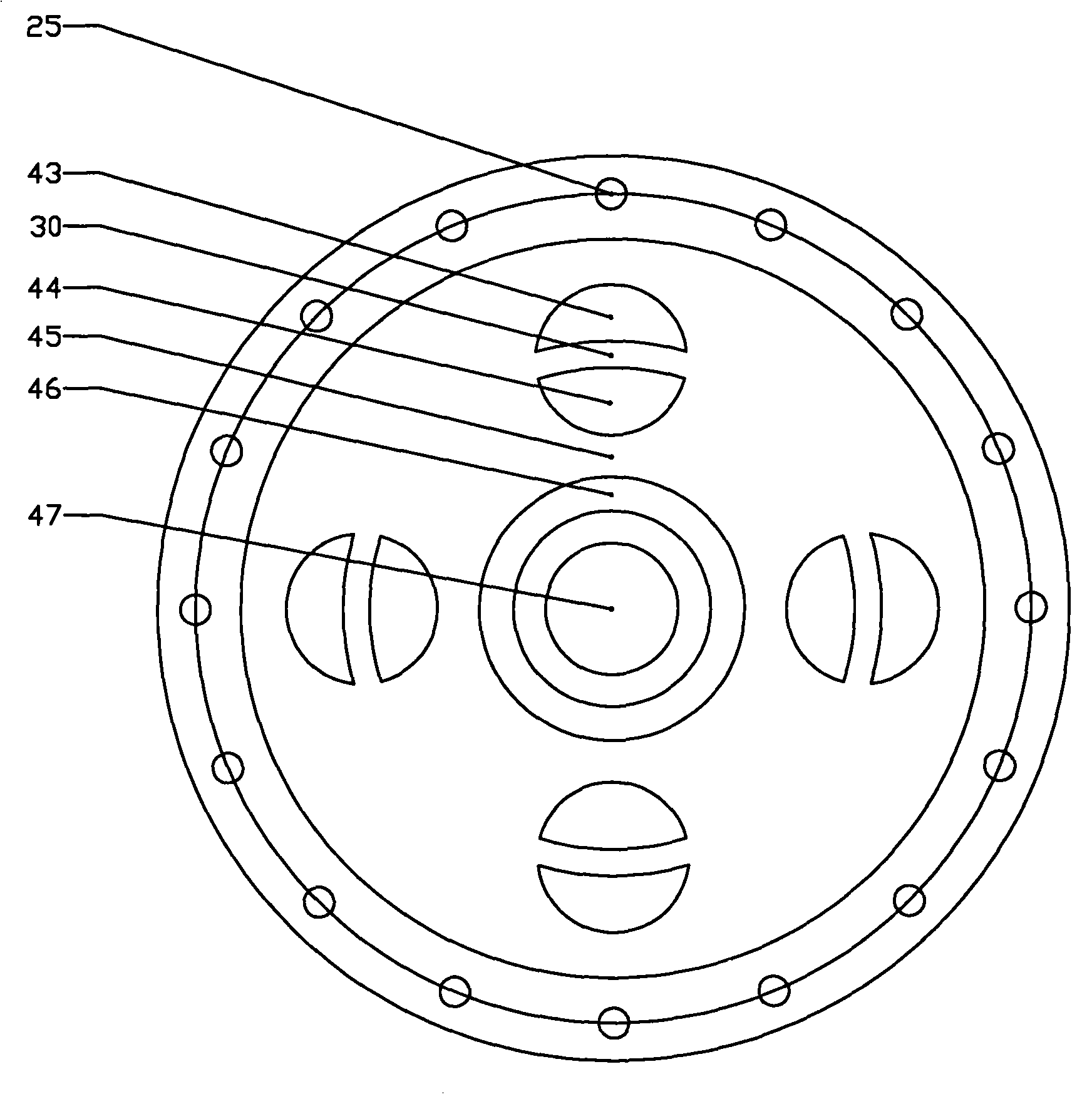
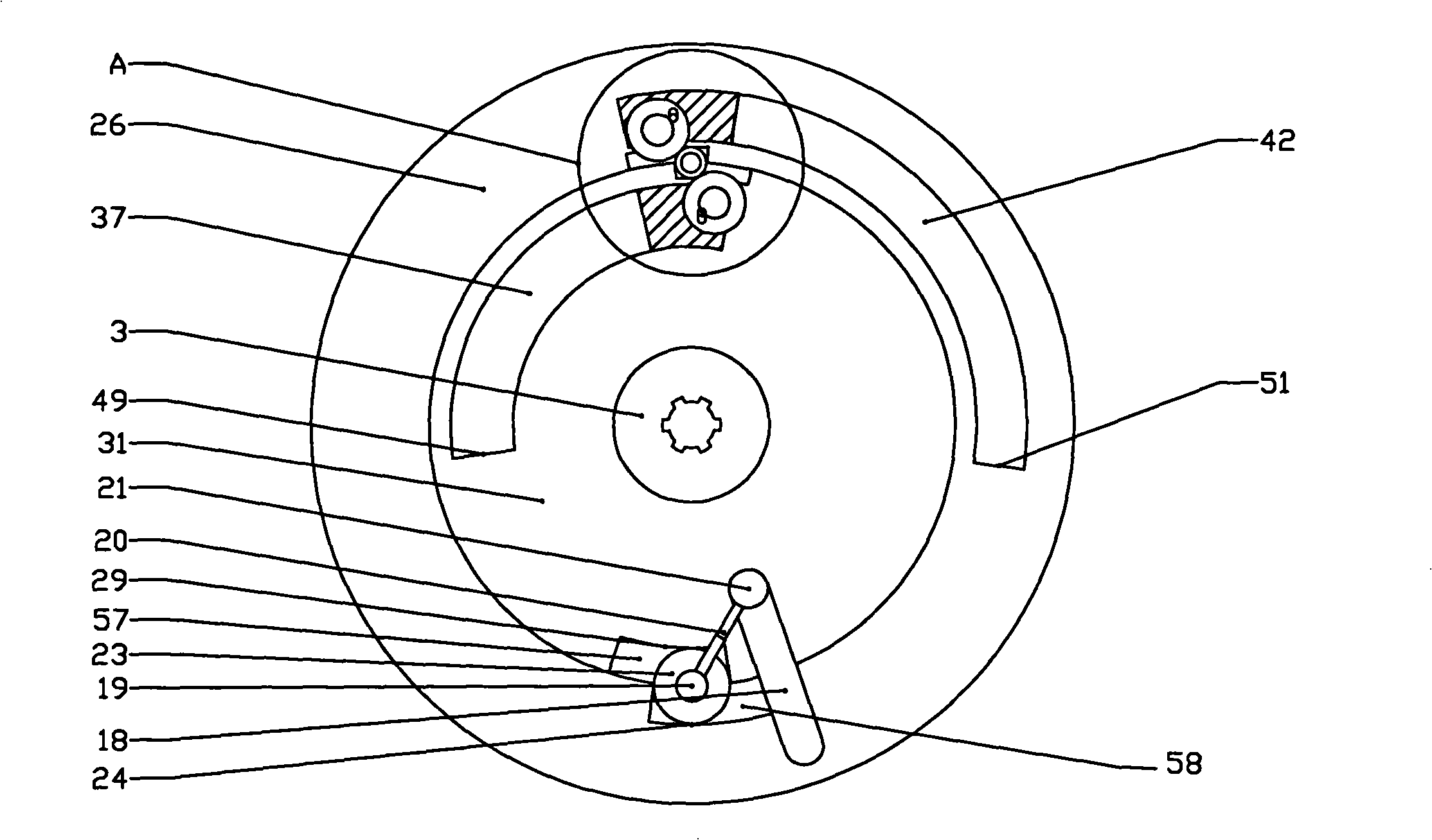
[0023] An automatic phase-changing internal-combustion engine gas distribution mechanism includes a combined turntable device, a phase-changing device and an air hole device. Refer to Figure 1 to image 3 , the air hole device comprises an air inlet 44 and an exhaust hole 43 corresponding to each cylinder 38 on the upper end surface of the cylinder body 28, each air inlet 44 and each exhaust hole 43 are respectively arranged on a circle, each air inlet 44 and a vent hole 43 are correspondingly distributed radially from inside to outside. Each air inlet 44 and a corresponding air outlet 43 together form a circle, and the two are separated by an arc-shaped spacer bar 30 .

[0024] Referring to FIG. 1 and FIG. 2 , the combined turntable device includes a main turntable 3 , an intake disk 31 , and an exhaust disk 26 . The main turntable 3 is rotatably assem...


PUM


Abstract

The invention relates to an automatically phase changing internal combustion engine which essentially comprising a combined rotary table, an air vent and a phase changing device. The combined rotary table comprises a main rotary table, an air inlet coil and an exhaust coil. The air vent comprises an air inlet hole and an exhaust hole formed by the upper end faces of a cylinder. The main rotary table is provided with a driving gear, a driven gear, a toggle gear and a sliding ball. A driving gear shaft is provided with a return spring and an expansion link. The air inlet groove of the air inlet coil is provided with an air inlet movable block; the exhaust groove of the exhaust coil is provided with an exhaust movable block. When an internal combustion engine works, the combined rotary table rotates above the air vent of the cylinder; when the rotating speed is changed, the sliding ball pushes the expansion link to rotate the driving gear under the mutual effect of centrifugal force and the return spring, so that the relative positions of the air inlet coil and the exhaust coil are changed, the air inlet movable block and the exhaust movable block are displaced, so as to increase or decrease the air inlet and the exhaust phases, and realize the effect that the valve distribution phase is automatically changed as the rotating speed.

Description

technical field [0001] The invention relates to a piston reciprocating gas distribution device for an internal combustion engine, in particular to a gas distribution mechanism for an internal combustion engine that can automatically change the gas distribution phase as the engine speed changes. Background technique [0002] The gas distribution phase of the internal combustion engine is related to its structural form, speed and other factors. The same internal combustion engine should have different gas distribution phases at different speeds. The higher the speed, the larger the advance angle and the lag angle. At present, the gas distribution mechanism of the known internal combustion engine is composed of two parts, the valve group and the valve train group. system. These two kinds of variable valve trains are basically composed of three parts: the control valve, the controller and the sensor under the control of the ECU, and the change of the valve phase is only unilate...

Claims


Application Information

Patent Timeline
Patent Type & Authority Applications(China)
IPC IPC(8): F01L1/34F01L13/00
Inventor 詹炳岳
Owner 詹炳岳
Learn More