Multi-use power module

A power module and multi-purpose technology, which is applied in the direction of output power conversion devices, electrical components, electric solid-state devices, etc., can solve the problems of increasing management and manufacturing costs

Active Publication Date: 2008-12-10
南京银茂微电子制造有限公司
View PDF0 Cites 11 Cited by
  • Summary
  • Abstract
  • Description
  • Claims
  • Application Information

AI Technical Summary

Problems solved by technology

Even from the same manufacturer, a wide variety ...

Method used


Image

  • Multi-use power module
  • Multi-use power module
  • Multi-use power module

Examples


Embodiment 1

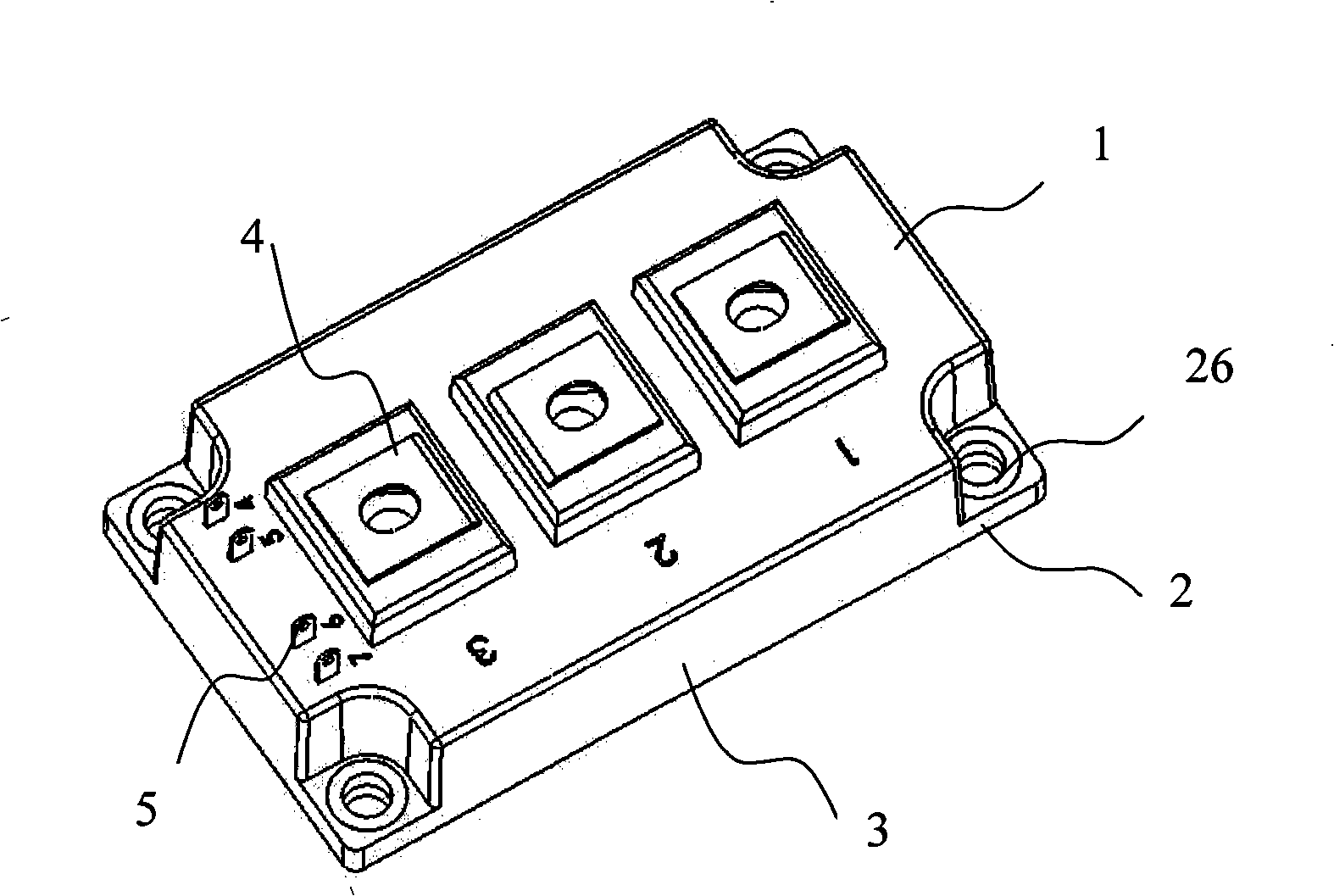
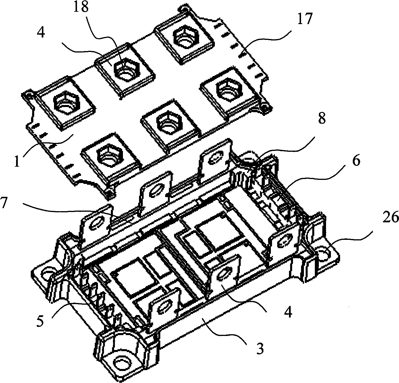
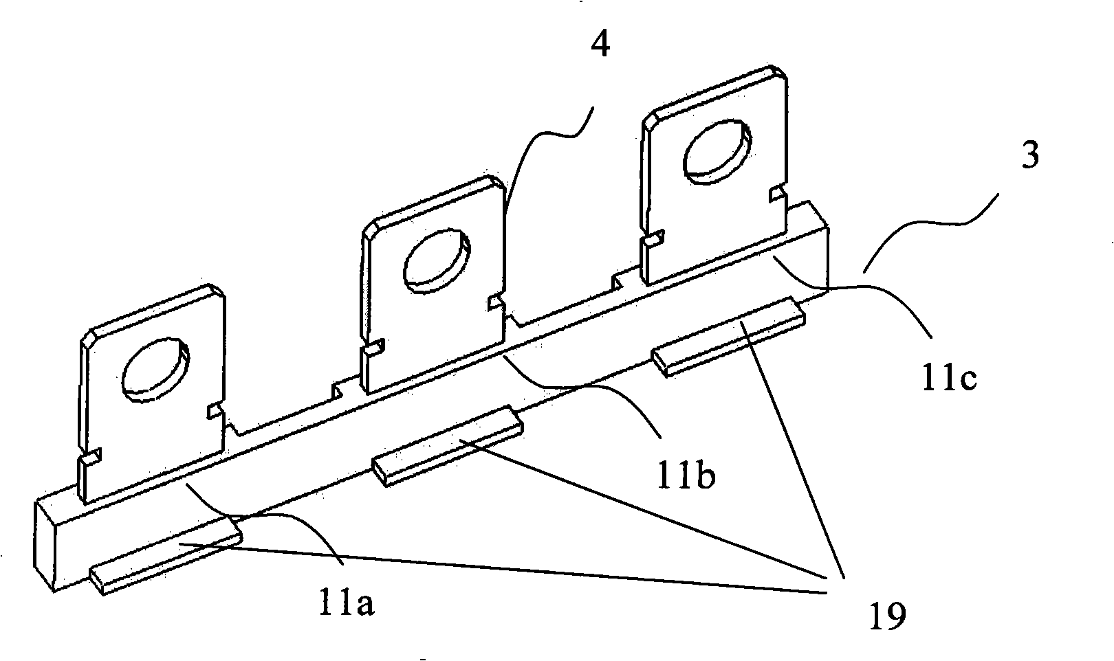
[0025] like figure 2 As shown, the multi-purpose power module 100 includes a top cover 1 , a bottom plate 2 , a frame 3 , a power terminal 4 and a signal terminal 5 , a power terminal support 7 and a signal terminal support 6 . The four corners of the bottom plate 2 are provided with mounting and positioning holes 26, and the bottom plate is provided with a DBC substrate and a chip. There are stoppers 8 at the four corners of the frame 3 , two power terminal brackets 7 are respectively embedded in the space between the front and rear sides of the frame 3 and the stoppers 8 , and the two signal terminal brackets 6 are respectively embedded in the left and right sides of the frame 3 and space between stops 8. Three power terminal holes 18 are respectively provided on the front and rear sides of the top cover 1 , and the distance between two adjacent power terminal holes 18 is equal, and six signal terminal holes 17 are respectively provided on the left and right sides of the t...

Embodiment 2

[0030] In this embodiment, the power module is used as a three-phase full bridge plus a chopper structure, such as Figure 7 As shown, a first power terminal 41a, a second power terminal 42a, and a third power terminal 43a are respectively provided in the first to third power terminal jacks on the first power terminal bracket located in the front of the frame 3, which are respectively used as The DC+, DC- and chopper power terminals are drawn out and installed on the power terminal holes 18 on the top cover 1 respectively. A first power terminal 41b, a second power terminal 42b, and a third power terminal 43b are respectively provided in the first to third power terminal jacks on the second power terminal bracket located in the rear of the frame 3, which are respectively U, V , W output power terminals are drawn out and installed on the power terminal holes 18 on the top cover 1 respectively. A total of seven groups of signal terminals 5 are arranged on the first signal termi...

Embodiment 3

[0032] In this embodiment, the power module is constructed as a half bridge or a chopper. like Figure 8 As shown, a first power terminal 41a, a second power terminal 42a, and a third power terminal 43a are respectively provided in the first to third power terminal jacks on the first power terminal bracket located in the front of the frame 3, which are respectively used as The U, V, W output power terminals are drawn out and installed on the power terminal holes 18 on the top cover 1 respectively. Two groups of five signal terminals 5 are arranged on the first signal terminal bracket and the second signal terminal bracket in the left and right sides of the frame 3. They are drawn out through the signal terminal holes 17 on the top cover and distributed on the left and right sides of the module. .


PUM


Abstract

The invention relates to a multipurpose power module with stronger current output range suitable for a plurality of circuit structures and a plurality of voltages, with one technical scheme: a multipurpose power module, including a top cover, a bottom plate, a frame, a power terminal and a signal terminal, wherein the DBC base plate and a chip are arranged on the bottom plate, and mounting location holes are arranged on the four angles of the base plate, characterized in that, the power module also includes a power terminal frame and a signal terminal frame. Three power terminal jacks are arranged on the power terminal frame, and the distance between the adjacent two power terminal jacks is equal, according to the using requirement of the power module, the power terminal is arranged in the power terminal jack. A signal terminal jack is arranged on the signal terminal frame, according to the using requirement of the power module, the signal terminal is arranged in the signal terminal jack. The power terminal frame is embedded in the front side of the frame or the inner side of the back side, wherein the signal terminal frame is embedded in the left side of the frame or the inner side of the right side.

Description

technical field [0001] The present invention relates to a power device, and more particularly to a power module which can be applied to various circuit structures and various voltages and has a larger current output range. Background technique [0002] Since MOSFET and IGBT power modules have a wide range of industrial applications, they are designed with different voltage and current levels. For example, the withstand voltage range of MOSFET modules can be from 60V to 600V, and the withstand voltage range of IGBT modules can be from 600V to 6500V. On the other hand, for power modules of the same withstand voltage level, the output current is also very different according to the size of the load. For example, for IGBT modules with a voltage level of 1200V, the output current range can be increased from 50 amps to over 1000 amps. Furthermore, for different applications, the design of MOSFET and IGBT modules has different circuit structures, such as single-tube, half-bridge,...

Claims


Application Information

Patent Timeline
IPC IPC(8): H02M1/00H01L23/48H01L25/00
CPCH01L2924/0002
Inventor 庄伟东
Owner 南京银茂微电子制造有限公司
Why Eureka
Try Eureka