Power terminal having built-in power terminal

A technology of power terminals and power modules, applied in the direction of output power conversion devices, electrical components, electric solid devices, etc., can solve the problems of increasing management and manufacturing costs, and achieve the effect of reducing costs and simplifying the bonding process

Active Publication Date: 2009-06-10
南京银茂微电子制造有限公司
View PDF0 Cites 12 Cited by
  • Summary
  • Abstract
  • Description
  • Claims
  • Application Information

AI Technical Summary

Problems solved by technology

Even from the same manufacturer, a wide variety of modules increases management and manufacturing costs

Method used


Image

  • Power terminal having built-in power terminal
  • Power terminal having built-in power terminal
  • Power terminal having built-in power terminal

Examples


Embodiment 1

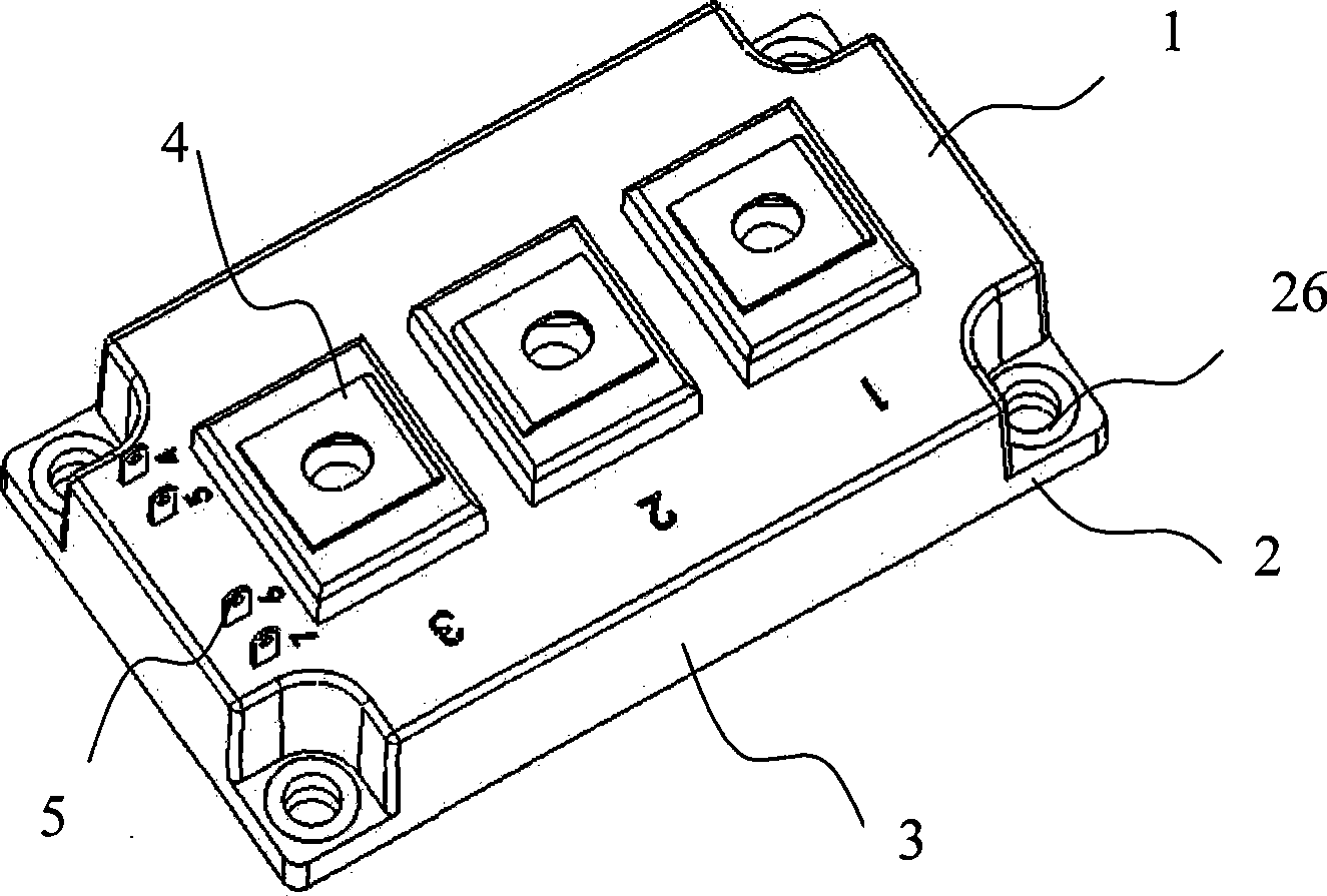
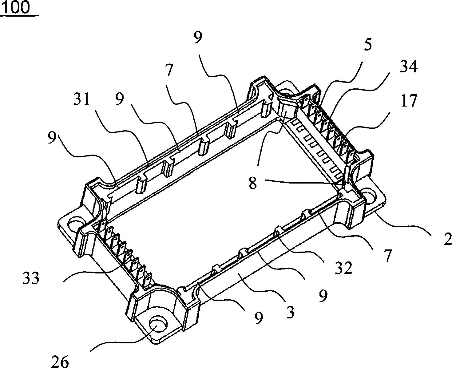
[0025] like figure 2 As shown, the power module 100 with embedded power terminals includes a top cover, a bottom plate 2 , a frame 3 , power terminals 4 and signal terminals 5 , and a power terminal bracket 7 and a signal terminal bracket 6 . The four corners of the bottom plate 2 are provided with mounting positioning holes 26, and the bottom plate is provided with a DBC substrate and a chip. The power terminal brackets 7 are arranged inside the front and rear sides 31, 32 of the frame 3, and molded together with the inside of the frame 3. Three slots 9 are respectively provided on the two power terminal brackets 7.

[0026] like image 3 As shown, the power terminals 4 are inserted into the three slots 9 at the front side 31 of the frame, the main body 41 of the power terminals is disposed in the slots 9 , and the bottom 42 of the power terminals is bonded to the bottom plate 2 . The notch 11 of the slot is provided with a bend 12, and the bend surface forms a 45° wedge. ...

Embodiment 2

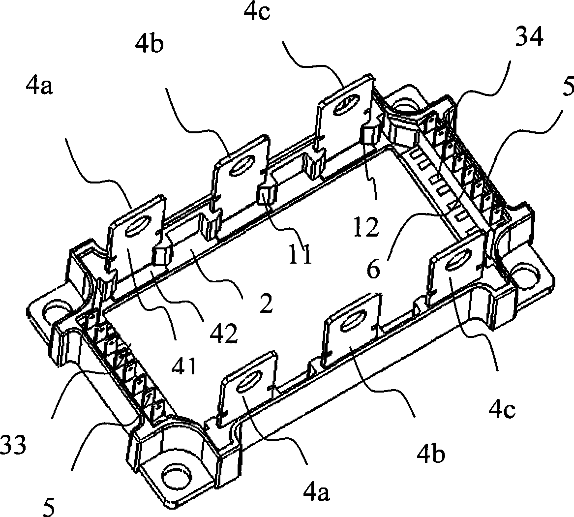
[0031] The difference between this embodiment and the above example is that this embodiment is provided with three power terminals 4 .

[0032] like Figure 5 As shown, in this embodiment, a first power terminal 4a, a second power terminal 4b, and a third power terminal 4c are respectively provided in three slots 9 located inside the front edge 31 of the frame. The two signal terminal brackets 6 are respectively embedded in the inner side of the left side 33 and the right side 34 of the frame 3, and the two ends of the left side 33 and the right side 34 are provided with stoppers 8 for the positioning of the signal terminal bracket 6, and the two signal terminal brackets 6 are respectively Two signal terminals 5 are provided.

[0033] In this embodiment, the power module can directly replace the standard "34mm" power module under the condition that the installation positioning hole remains unchanged.

Embodiment 3

[0035] In this embodiment, the power module has a half-bridge structure.

[0036] As shown in Figure 6, there are three slots 9 located in the front side 31 of the frame 3, and are respectively provided with a first power terminal 4a, a second power terminal 4b, and a third power terminal 4c, which serve as U, V, W respectively. The output power terminals are led out, and two signal terminals 5 are respectively provided on the two signal terminal brackets in the left side 33 of the frame 3 .


PUM


Abstract

The invention relates to a power module with an embedded power terminal. The module can accommodate a plurality of circuit structures, can make the output current range of the module with the same dimension maximized through the combination of lead wire terminals, has a simple structure and is convenient to replace. The power module comprises the following technical proposal to realize the aim: the power module with the embedded power terminal comprises a top cover, a base plate, a side frame, a power terminal and a signal terminal; the side frame extends upwards along the periphery of the base plate; the inner wall of the side frame is provided with the power terminal and the signal terminal; the base plate is provided with a circuit substrate and a chip; the inner side of at least one side of the side frame is provided with a slot; a power terminal main body is arranged in the slot; and the bottom of the power terminal is bonded with the base plate.

Description

technical field [0001] The invention relates to a power device, more specifically to a power module with embedded power terminals which is applicable to various circuit structures and voltages and has a large current output range. This invention is suitable for power modules that use nuts / bolts to secure the power terminals. Background technique [0002] Because MOSFET and IGBT power modules have a wide range of industrial applications, their designs exist in different voltage and current levels. For example, the withstand voltage of MOSFET modules can range from 20V to 1000V, while the withstand voltage of IGBT modules can range from 300V to 6500V. On the other hand, for power modules with the same withstand voltage level, the output current is also very different according to the size of the load. For example, for 1200V IGBT modules, the range of output current can be increased from 50 amps to more than 1000 amps. Furthermore, for different applications, the design of M...

Claims


Application Information

Patent Timeline
Patent Type & Authority Applications(China)
IPC IPC(8): H02M1/00H01L23/48H01L25/00
CPCH01L2924/0002
Inventor 庄伟东
Owner 南京银茂微电子制造有限公司
Why Eureka
Try Eureka