

Multi-use power module
A power module and multi-purpose technology, which is applied in the direction of output power conversion devices, electrical components, electric solid-state devices, etc., can solve the problems of increasing management and manufacturing costs
Active Publication Date: 2011-05-25
南京银茂微电子制造有限公司
View PDF0 Cites 0 Cited by
- Summary
- Abstract
- Description
- Claims
- Application Information
AI Technical Summary
Problems solved by technology
Even from the same manufacturer, a wide variety of modules increases management and manufacturing costs
Method used
View moreImage
Smart ImageViewing Examples

Examples
Embodiment 2
[0020] Figure 7 It is a combination structure diagram of power terminals and signal terminals in Embodiment 2 of the present invention
Embodiment 3
[0021] Figure 8 It is a combined structure diagram of power terminals and signal terminals in Embodiment 3 of the present invention
Embodiment 4
[0022] Figure 9 It is a combined structure diagram of power terminals and signal terminals in Embodiment 4 of the present invention
Login to View More PUM
 Abstract
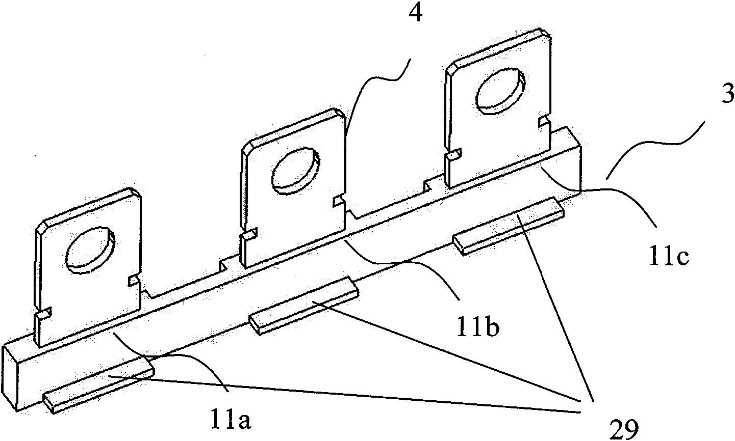
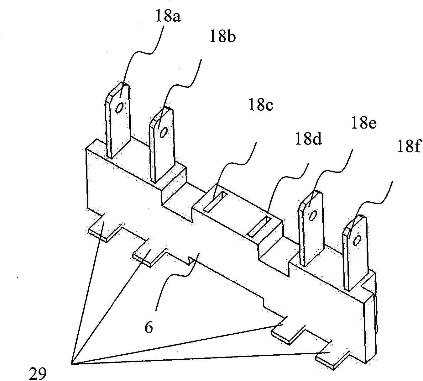
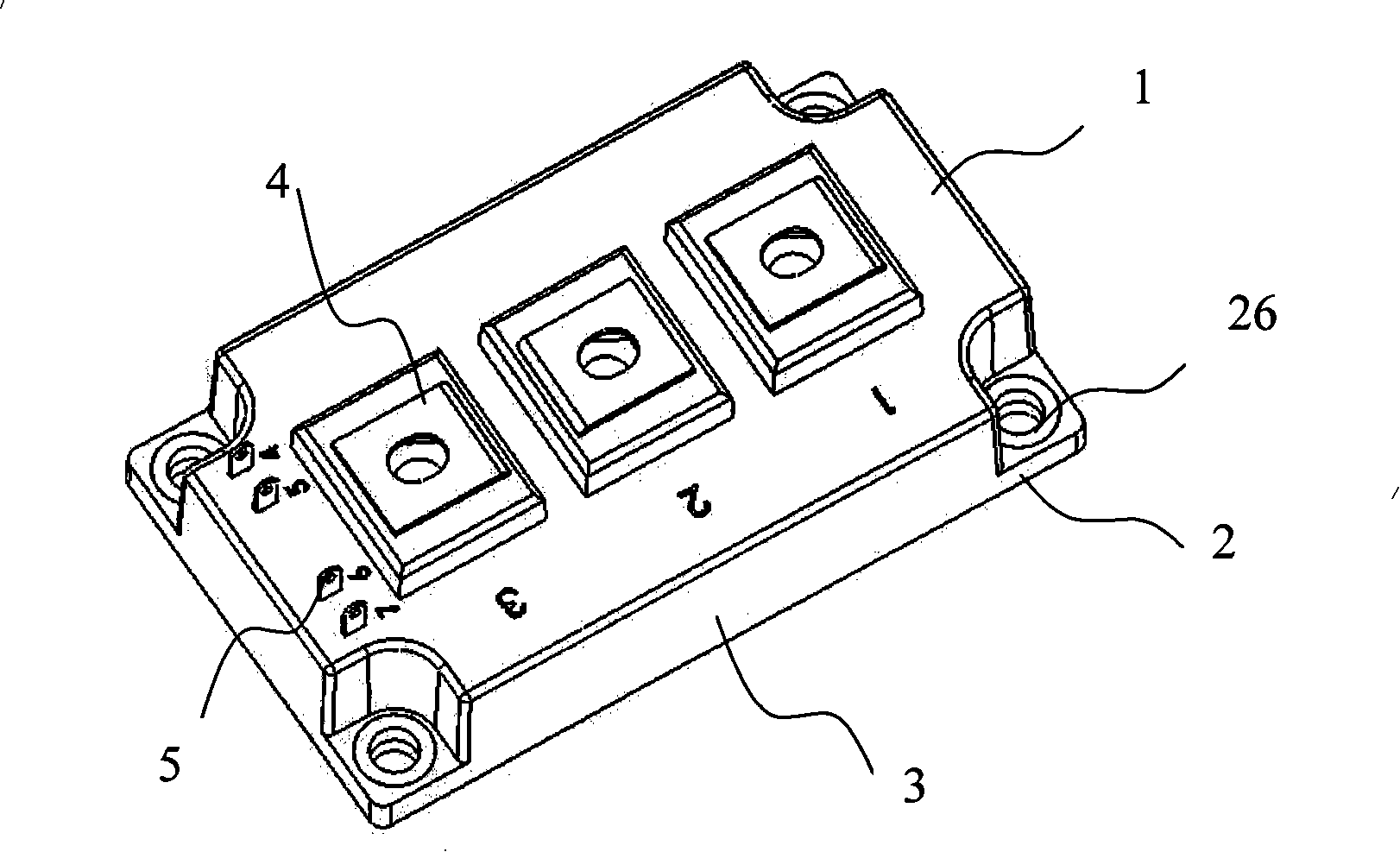
The invention relates to a multipurpose power module with stronger current output range suitable for a plurality of circuit structures and a plurality of voltages, with one technical scheme: a multipurpose power module, including a top cover, a bottom plate, a frame, a power terminal and a signal terminal, wherein the DBC base plate and a chip are arranged on the bottom plate, and mounting location holes are arranged on the four angles of the base plate, characterized in that, the power module also includes a power terminal frame and a signal terminal frame. Three power terminal jacks are arranged on the power terminal frame, and the distance between the adjacent two power terminal jacks is equal, according to the using requirement of the power module, the power terminal is arranged in the power terminal jack. A signal terminal jack is arranged on the signal terminal frame, according to the using requirement of the power module, the signal terminal is arranged in the signal terminal jack. The power terminal frame is embedded in the front side of the frame or the inner side of the back side, wherein the signal terminal frame is embedded in the left side of the frame or the inner side of the right side.
Description
technical field [0001] The invention relates to a power device, more specifically to a power module which is applicable to various circuit structures and voltages and has a relatively large current output range. Background technique [0002] Because MOSFET and IGBT power modules have a wide range of industrial applications, their designs exist in different voltage and current levels. For example, the withstand voltage of MOSFET modules can range from 60V to 600V, while the withstand voltage of IGBT modules can range from 600V to 6500V. On the other hand, for power modules with the same withstand voltage level, the output current is also very different according to the size of the load. For example, for 1200V IGBT modules, the range of output current can be increased from 50 amps to more than 1000 amps. Furthermore, for different applications, the design of MOSFET and IGBT modules has different circuit structures, including single transistor, half-bridge, chopper, symmetric...
Claims
Login to View More Application Information
Patent Timeline
 Patent Type & AuthorityPatents(China)
IPC IPC(8): H01L25/00H01L23/48H02M1/00
CPCH01L2924/0002
Inventor庄伟东
Owner南京银茂微电子制造有限公司