Micromechanical pressure sensor and corresponding production method

一种压力传感器、制造方法的技术,应用在微观结构装置、制造微观结构装置、微电子微观结构装置等方向,能够解决压力传感器耗费和成本升高等问题,达到简单正面组装可能性、小组装高度的效果

Inactive Publication Date: 2016-11-30
ROBERT BOSCH GMBH
View PDF12 Cites 4 Cited by
  • Summary
  • Abstract
  • Description
  • Claims
  • Application Information

AI Technical Summary

Problems solved by technology

The main reason for this is the required medium channel, which, in contrast to inertial sensors and magnetic field sensors, requires a medium channel for pressure sensors, which significantly increases the outlay and costs for encapsulating the pressure sensor

Method used


Image

  • Micromechanical pressure sensor and corresponding production method
  • Micromechanical pressure sensor and corresponding production method
  • Micromechanical pressure sensor and corresponding production method

Examples


Embodiment Construction

[0030] In the figures, identical reference numbers indicate identical or functionally identical elements.

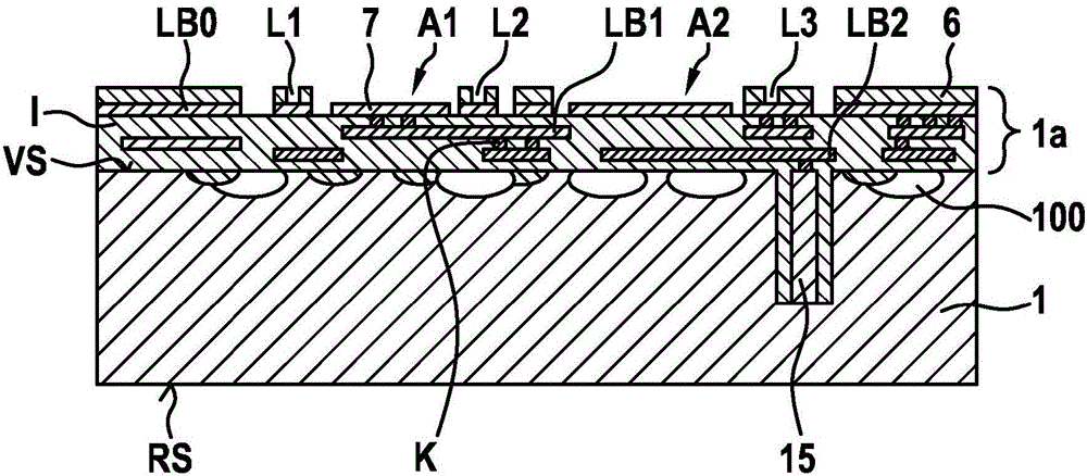
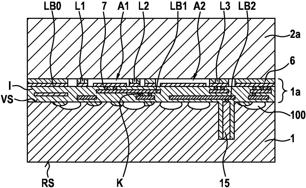
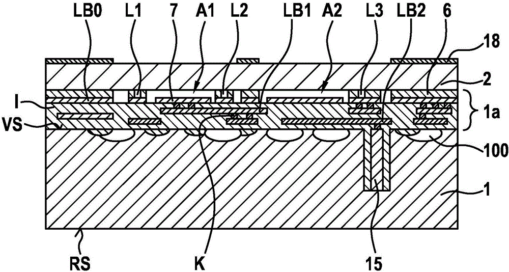
[0031] Figure 1a )-h) show schematic cross-sectional views of a micromechanical pressure sensor arrangement according to a first embodiment of the invention and a corresponding manufacturing method.

[0032] exist Figure 1a ), the reference numeral 1 designates a CMOS wafer with a plurality of CMOS circuits 100 including, for example, evaluation circuits for the micromechanical pressure sensor arrangement to be formed.

[0033] The CMOS wafer has a front side VS and a back side RS. On the front side VS of the CMOS wafer 1, a rewiring device 1a is formed, the rewiring device 1a having a plurality of printed conductor layers LB0, LB1, LB2 and an insulating layer I between these printed conductor layers LB0, LB1, LB2 . In order to simplify the illustration, the insulating layer I in which the conductor track layers LB0 , LB1 , LB2 are embedded is not shown separately. ...


PUM


Abstract

The invention relates to a micromechanical pressure sensor and to a corresponding production method. The micromechanical pressure sensor comprises: an ASIC wafer (1) with a front face (VS) and a rear face (RS); a wiring system (1a) formed on the front face (VS), said system having a plurality of conductor path planes (LB0, LB1, LB2) and insulation layers (I) lying therebetween; a patterned insulation layer (6) formed above an uppermost conductor path plane (LB0) of the plurality of conductor path planes (LB0, LB1, LB2); a micromechanical functional layer (2; 2") on the insulation layer (6), said functional layer having a membrane region (M; M'; M"), which can be supplied with pressure and acts as a first pressure detection electrode, above a cavity (A1; A1 ") in the insulation layer (6); and a second pressure detection electrode (7; 7") on the uppermost conductor path plane (LB0), said second electrode being formed in the cavity (A1; A1"), being spaced from the membrane region (M; M'; M") and being electrically insulated from said membrane region (M; M'; M"). The membrane region (M; M'; M") is electrically connected to the uppermost conductor path plane (LB0) by one or more first contact plugs (P1, P2; P1", P2") running through the membrane region (M; M'; M") and through the insulation layer (6).

Description

technical field [0001] The invention relates to a micromechanical pressure sensor arrangement and a corresponding production method. Background technique [0002] Although any desired micromechanical structural elements can be used, the invention and the problem to be solved by the present invention are only explained with the aid of structural elements on a silicon substrate. [0003] Micromechanical sensor devices for measuring eg acceleration, rotational speed, magnetic field and pressure are generally known and produced on a large scale for different applications in the automotive and consumer sectors. Trends in consumer electronic devices are especially miniaturization of structural components, functional integration and effective cost reduction. [0004] At present, the acceleration sensor and the rotational speed sensor as well as the acceleration sensor and the magnetic field sensor have been manufactured as a combined sensor (6d). In addition, there is a first 9d m...

Claims


Application Information

Patent Timeline
Patent Type & Authority Applications(China)
IPC IPC(8): G01L9/00B81C1/00
CPCB81B7/0061B81B7/02B81B2201/025B81B2201/0264B81C1/00246G01L9/0042G01L9/0073H01L2224/11
Inventor J·克拉森
Owner ROBERT BOSCH GMBH
Why Eureka
Try Eureka