
Combined service brake and stored-energy brake cylinder with internal ventilation

一种弹簧蓄能、制动缸的技术,应用在制动器、制动分泵、制动组件等方向

Inactive Publication Date: 2008-12-10
KNORR BREMSE SYST FUER NUTZFAHRZEUGE GMBH
View PDF1 Cites 10 Cited by
  • Summary
  • Abstract
  • Description
  • Claims
  • Application Information

AI Technical Summary

Problems solved by technology

On the other hand, the air volume flowing out through the exhaust valve can no longer be used to build up the operating braking force

Method used


Image

  • Combined service brake and stored-energy brake cylinder with internal ventilation
  • Combined service brake and stored-energy brake cylinder with internal ventilation
  • Combined service brake and stored-energy brake cylinder with internal ventilation

Examples


Embodiment Construction

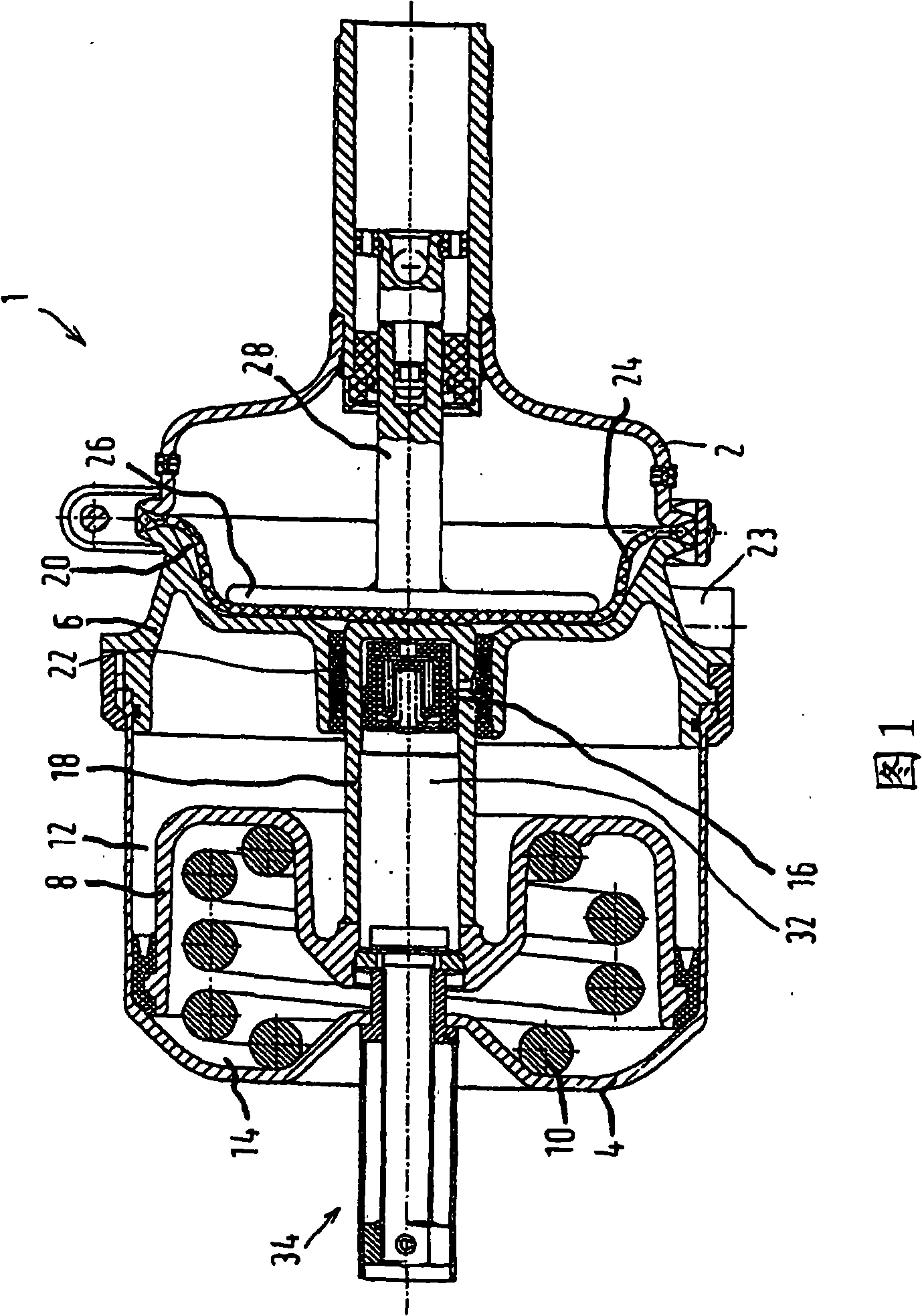
[0020] In order to explain the invention by way of example, FIG. 1 shows a combined service brake and spring-loaded brake cylinder 1 , referred to below as a combination cylinder. The combined cylinder comprises a working brake cylinder 2 and a spring-loaded brake cylinder 4 structurally and functionally associated with the working brake cylinder. Service brake cylinder 2 and spring-loaded brake cylinder 4 are separated from one another by an intermediate wall 6 . A spring-charged brake piston 8 is displaceably arranged in the spring-charged brake cylinder 4 , wherein a stored-charge spring 10 bears against one side of the spring-charged brake piston 8 . On the opposite side thereof, the energy storage spring 10 is supported on the bottom of the spring energy storage brake cylinder 4 . A spring-charged brake chamber 12 is formed between the spring-charged brake piston 8 and the intermediate wall 6 , which is connected to a pressure regulation module, not shown for reasons of ...


PUM


Abstract

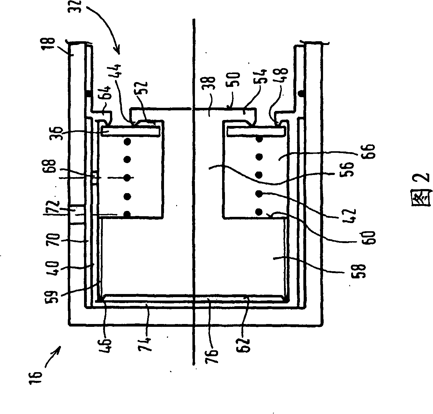
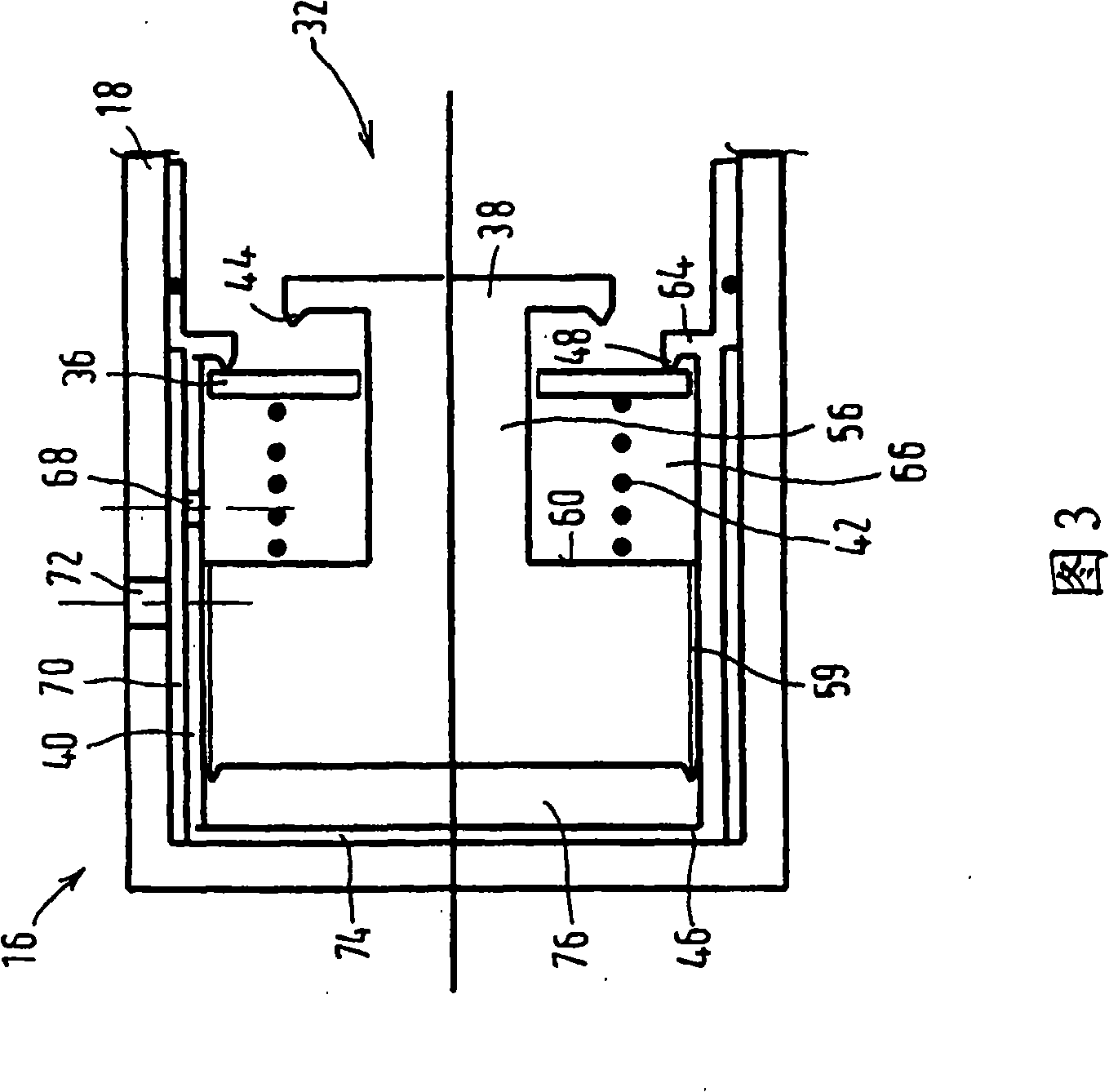
The invention relates to a combined service brake and the stored-energy brake cylinder (1) having: a) a diaphragm (24) which is arranged in a housing of the service brake cylinder (2) and to which pressure can be applied, said diaphragm (24) bounding on one side a brake chamber (20) to which service brake pressure can be applied and on the other side a chamber which holds a restoring spring, b) a stored-energy brake piston (8) which is arranged in a housing of the stored-energy brake cylinder (4) and can be activated by a pre-loaded spring (10), said stored-energy brake piston (8) bounding on one side a stored-energy brake chamber (12) and on the other side a spring chamber (14) which holds a pre-loaded spring (10), and the said stored-energy brake piston (8) having a piston rod (18) which is fitted with a ventilation valve (16); which forms or shuts off a flow connection between the spring chamber (14) and the service brake chamber (20), which combined service brake and stored-energy brake cylinder (1) is characterized by the fact that the ventilation valve (16) has the following features: c) a piston (38) which is fitted with a valve body (36) is provided, said piston (38) being guided in an axially displaceable fashion in a cylinder (40) which is formed on the piston rod (18), d) at least one compression spring (42) which is supported on the piston (38) loads the valve body (36) against a first valve seat (44) on the piston (38) and against a second valve seat (48) on the cylinder (40), e) the valve body (36) is loaded by the pressure in the spring chamber (14) in a direction which lifts it off from the first valve seat (44) and from the second valve seat (48), f) the piston (38); is loaded by the pressure in the service brake chamber (20) in a direction which forces the first valve seat (44) against the valve body (36) and lifts off the valve body (36) from the second valve seat (48).

Description

technical field [0001] The invention relates to a combined service brake and spring-loaded brake cylinder according to the preamble of claim 1, comprising a pressure-loadable diaphragm arranged in the housing of the service brake cylinder, which diaphragm is On one side, a working brake cavity that can be loaded with working brake pressure is defined, and on the other side, a cavity for receiving a return spring is defined; a spring-energized brake piston operated by a stored-energy spring, which defines on one side a spring-charged brake chamber and on the other side a spring chamber receiving a stored-energy spring, and There is a piston rod with a vent valve which establishes or closes the flow communication between the spring chamber and the working brake chamber. Background technique [0002] One such combined operating brake and spring-loaded brake cylinder is known, for example, from DE 4011739 A1. On the other side, the vent valve is arranged in the end of the holl...

Claims


Application Information

Patent Timeline
Patent Type & Authority Applications(China)
IPC IPC(8): B60T17/08F16D65/28
CPCB60T17/08B60T17/083
Inventor N·萨瓦尼A·朔德洛斯基
Owner KNORR BREMSE SYST FUER NUTZFAHRZEUGE GMBH
Learn More