Motorcycle

A technology for motorcycles and car bodies, applied in mechanical equipment, engine components, machines/engines, etc., can solve the problems of increased high-frequency components of exhaust sound and increased speed of sound.

Active Publication Date: 2012-08-08
YAMAHA MOTOR CO LTD
View PDF1 Cites 0 Cited by
  • Summary
  • Abstract
  • Description
  • Claims
  • Application Information

AI Technical Summary

Problems solved by technology

This causes the speed of sound to increase, causing an increase in the high frequency components of the exhaust sound

Method used


Image

  • Motorcycle
  • Motorcycle
  • Motorcycle

Examples


Embodiment Construction

[0038] Referring to the drawings, embodiments of the present invention will be described with reference to the drawings. In the following description, the upstream side and the downstream side are defined on the basis of the flow of exhaust gas.

[0039] (1) The structure of the motorcycle.

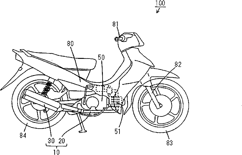
[0040] figure 1 is a side view of a motorcycle according to an embodiment of the present invention.

[0041] figure 1 The motorcycle 100 shown includes a body 80 comprised of a body frame and a frame cover. A head pipe (not shown) is provided at the front of the vehicle body 80, and a handlebar 81 is provided at the upper end of the head pipe. A front fork 82 is attached to the lower end of the head pipe. In this state, the front fork 82 is rotatable about the axis of the head pipe within a predetermined angle range. A front wheel 83 is rotatably supported on the lower end of the front fork 82 . Rear wheels 84 are rotatably supported at the rear of the vehicle body 80 . The single...


PUM


Abstract

An exhaust pipe into which an exhaust gas from a single cylinder engine flows is provided with a three way catalyst. The exhaust pipe includes a first pipe inserted into a muffler and a second pipe extending toward the downstream side from the first pipe within the muffler. A narrowed portion having an inner diameter smaller than that of a cylindrical portion of the first pipe is provided in a downstream-end opening of the first pipe. The narrowed portion is inserted into an upstream-end opening of the second pipe. A first expansion chamber that integrally encloses the outer periphery and thedownstream-end opening of the second pipe is formed within the muffler. A plurality of holes are formed in a distributed manner in a region, except a downstream region, of a peripheral surface of thesecond pipe. The length in the axial direction of the downstream region is not less than 1 / 3 times the inner diameter of the second pipe.

Description

technical field [0001] The invention relates to a motorcycle comprising an exhaust device. Background technique [0002] Conventionally, various mufflers have been developed in order to reduce exhaust sound due to exhaust emissions from engines of automobiles (for example, see JP 60-37287B). [0003] The muffler disclosed in JP 60-37287B has a perforated pipe and an outer cylinder. A perforated tube is inserted into the outer cylinder. A resonance chamber is formed between the outer peripheral surface of the perforated pipe and the inner peripheral surface of the outer cylinder. An expansion chamber is formed on the downstream side of the resonance chamber in the outer cylinder. The resonance chamber and the expansion chamber are separated by a partition plate. The inner space of the perforated plate communicates with the resonance chamber through the holes of the perforated tube. In addition, the downstream end of the perforated tube opens into the expansion chamber. ...

Claims


Application Information

Patent Timeline
Patent Type & Authority Patents(China)
IPC IPC(8): F01N1/08F01N7/08
CPCF01N1/089F01N2470/04F01N2340/02F01N2590/04F01N2470/20F01N2470/30F01N3/2885F01N1/08
Inventor 味户智史
Owner YAMAHA MOTOR CO LTD
Why Eureka
Try Eureka