
Optical tilt sensor

A light detector and light source technology, which is applied in the direction of using optical devices, instruments, measuring devices, etc., can solve the problems of difficulty in accessing objects and limited space for installing sensors.

Inactive Publication Date: 2008-12-17
HONG KONG APPLIED SCI & TECH RES INST
View PDF0 Cites 4 Cited by
  • Summary
  • Abstract
  • Description
  • Claims
  • Application Information

AI Technical Summary

Problems solved by technology

However, measuring or monitoring tilt is not trivial due to difficulties such as difficult access to the object, limited space for installing sensors near the object, and other known difficulties familiar to those skilled in the art

Method used


Image

  • Optical tilt sensor
  • Optical tilt sensor
  • Optical tilt sensor

Examples


Embodiment Construction

[0035] Detailed Description of Preferred Embodiments

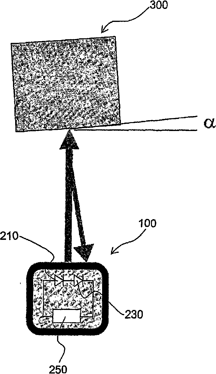
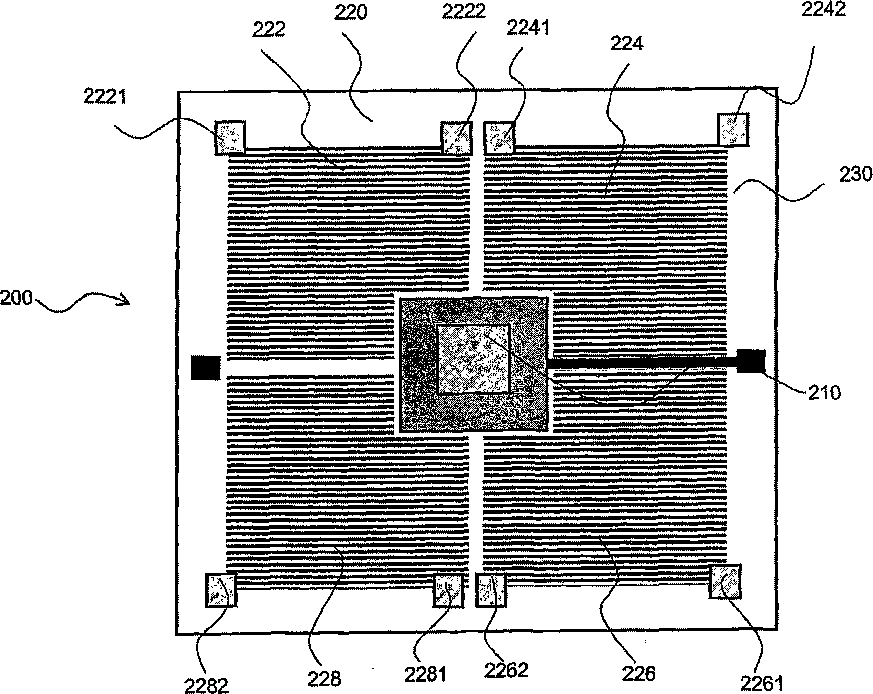
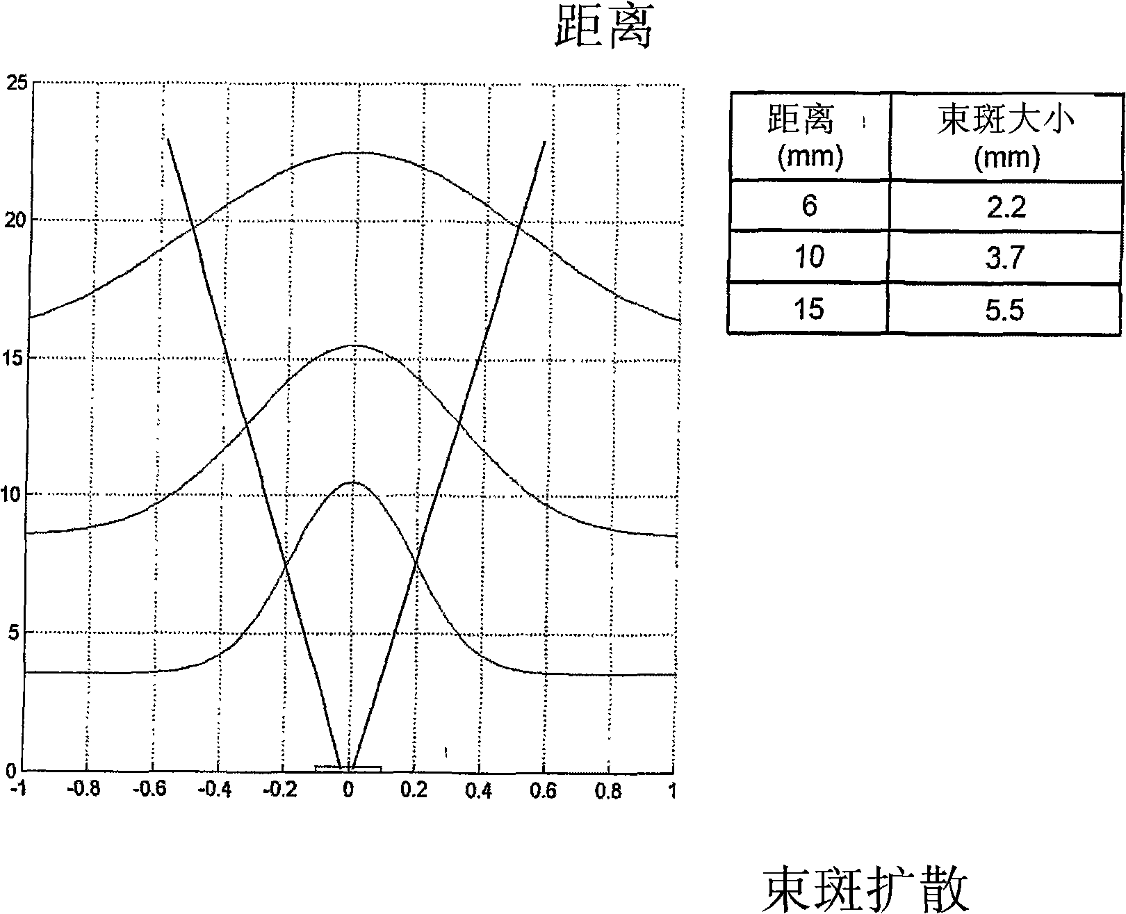
[0036] refer to figure 1 and 2 , an optical sensor 100 comprising figure 2 The optoelectronic device is used to measure the tilt of the object 300. figure 2 The optoelectronic device 200 includes a light source 210 and a photodetector 220 mounted on a common support structure 230 . The light source 210 suitably emits a beam of light toward an object, which is then reflected back to the light detector 220 . An example of a suitable light source for this application is a VCSEL (Vertical Cavity Surface Emitting Laser) laser source. Photodetector 220 is adapted to receive a light beam from a light source and includes a plurality of discrete photodetection regions (222, 224, 226, 228). Each photodetection region is itself a photodetector responsively and adapted to detect a wavelength of light emitted by the laser source. Besides the optoelectronic device, the light sensor also includes a differential circuit and a cont...


PUM


Abstract

An optoelectronic device comprises an optical source (210) and an optical detector (220), the optical source being adapted for emitting an optical beam for subsequent reflection towards the optical detector (220), the optical detector (220) being adapted for receiving the optical beam and comprising a plurality of discrete optical detection regions (222,224,226,228) for converting an optical beam into electrical energy and the optical detection regions (222,224,226,228) are arranged so that an electrical characteristic of the optical detector (220) is dependent on the relative distribution of an incident optical beam on the plurality of optical detection regions (222,224,226,228).

Description

field of invention [0001] The present invention relates to optoelectronic devices, in particular to optoelectronic devices for monitoring the tilt or displacement of objects. The invention also relates to a photoelectric sensor for sensing tilt, displacement and motion. Background of the invention [0002] For many applications, it is important to monitor and / or measure the tilt, displacement or movement of an object. For example, monitoring the tilt of an object will provide important information about the object's stability or other conditions. However, measuring or monitoring tilt is not trivial due to difficulties such as difficulty in accessing the object, limited space for mounting sensors near the object, and other known difficulties familiar to those skilled in the art. [0003] purpose of invention [0004] Accordingly, it is an object of the present invention to provide a sensor for monitoring the tilt, movement or displacement of an object. At a minimum, the i...

Claims


Application Information

Patent Timeline
Patent Type & Authority Applications(China)
IPC IPC(8): G01B11/26
CPCG01B11/26
Inventor 托斯腾·威匹耶斯基
Owner HONG KONG APPLIED SCI & TECH RES INST
Learn More