Beaming method of warp shaft

A warp yarn and yarn shaft technology is applied in the warping field of warp yarn shafts, which can solve the problems of heavy burden, time-consuming, complicated and other problems, and achieve the effect of rapid operation.

Inactive Publication Date: 2009-01-07
TSUDAKOMA KOGYO KK
View PDF3 Cites 15 Cited by
  • Summary
  • Abstract
  • Description
  • Claims
  • Application Information

AI Technical Summary

Problems solved by technology

In the past, these tasks were performed manually by operators, and they became very complicated and labor-intensive tasks.

Method used


Image

  • Beaming method of warp shaft
  • Beaming method of warp shaft
  • Beaming method of warp shaft

Examples


Embodiment Construction

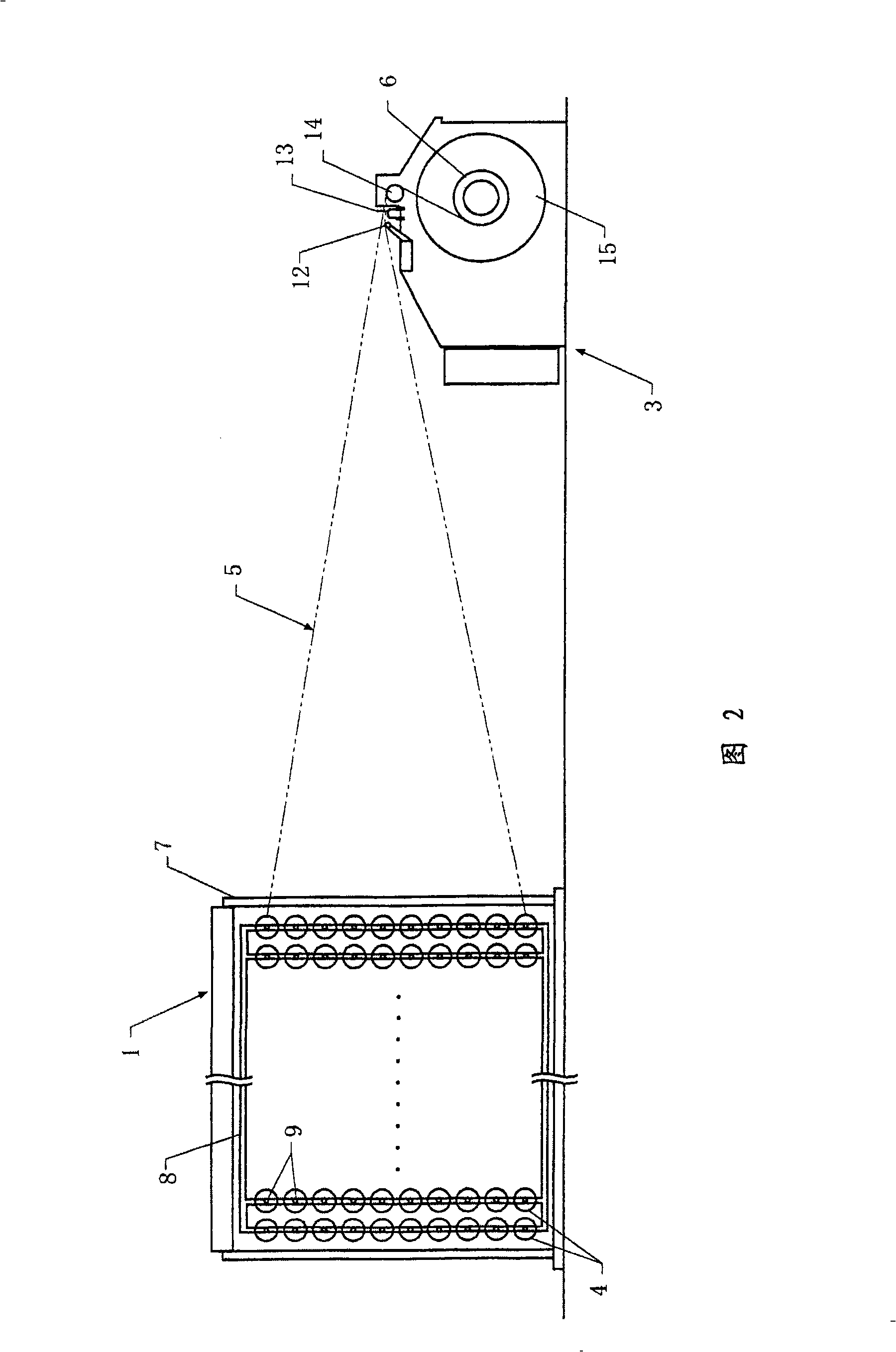
[0024] As shown in Figure 2 and Figure 3, the warping device used in the warping method of the warp beam is composed of a warp creel device 1 and a winding device 3 as main devices. The yarn body 4 draws out the yarn group 5 , and after the yarn group 5 is arranged into a sheet shape, it is wound by the winding device 3 to form a warp beam 6 .

[0025] The warp creel device 1 has a V-shaped machine frame 7 for supporting a plurality of yarn supply bodies 4, and the yarn supply body frame 8 is fixed on the inside of the machine frame 7. M×N yarn supply bodies 4 are rotatably supported approximately around the horizontal axis 9 at intervals. The yarn drawn from each yarn supply body 4 forms a yarn group 5 via a yarn cut sensor 11 provided near the yarn supply body 4, and is led toward the winding device 3 side.

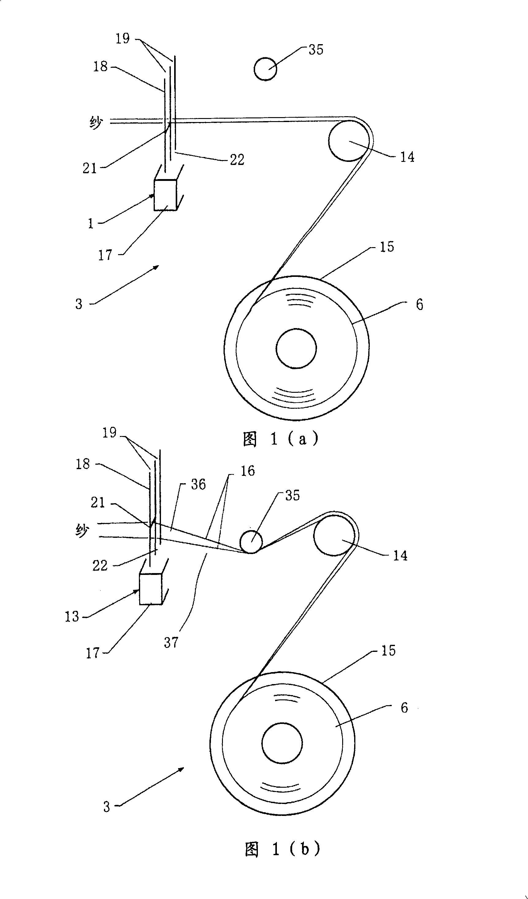
[0026] In the winding device 3 , a guide 12 , a reed 13 , and a guide roller 14 are sequentially arranged at intervals from the upstream side to the downstream side, a...


PUM


Abstract

The invention relates to a beaming method for warp shaft. the method comprises guiding a yarn set (5) guided from a plurality of yarn supply bodies (4) to a coiling apparatus (3) including a reed (13), in a beaming method for the warp shaft of forming the warp shaft by coiling into warp slice with the coiling apparatus, as the reed, reed with steps of a high step section (21) of a yarn through section (19) between reed needles (18) and a low non-step section (22) of the yarn through section are formed according specified space; after the coiling of the warp shaft, the yarn set and the reed with the step section are moved respectively, a portion of the yarn set is contacted with the step section, left section of the yarn set is divided into more than two unit warp slices by the upper part of the non-step section, separated belts are inserted into between a plurality of warp slices, and each unit warn slices are cut between the reed with step and the belt.

Description

technical field [0001] The invention relates to a method for warping warp beams used in a sizing and drying device. More specifically, it mainly relates to a method of warping warp beams prepared by a sizing and drying device for spun yarns by sizing and drying warp yarn sheets drawn from a plurality of warp beams together. Background technique [0002] Above-mentioned sizing and drying device is known, and as shown in Figure 9, in the warping process, several warp beams 6 that have been warped are arranged on the warp beam support 92 of yarn supply device 91, make the warp beam drawn from each warp beam The warp yarn sheets 93 merge and are sized together by the sizing device. After that, each warp yarn sheet is hung on a plurality of drying cylinders 96 equipped in the drying device 95 to be dried to form a warp yarn sheet 97. The unillustrated separating rod in the one separating region first separates the warp yarn sheets up and down, and then merges the separated warp ...

Claims


Application Information

Patent Timeline
Patent Type & Authority Applications(China)
IPC IPC(8): D02H3/00D02H13/16D02H13/28
Inventor 坚田洁田村俊晃
Owner TSUDAKOMA KOGYO KK
Why Eureka
Try Eureka