Axial spacing stopper pin device

A technology of axial limit and shaft pin, applied in the direction of mechanical equipment, connecting components, etc., can solve the problems of inconvenient use, troublesome disassembly and assembly, etc., and achieve the effects of quick disassembly, convenient operation and reliable use

Active Publication Date: 2010-12-08
MCC BAOSTEEL TECH SERVICE
View PDF1 Cites 0 Cited by
  • Summary
  • Abstract
  • Description
  • Claims
  • Application Information

AI Technical Summary

Problems solved by technology

The common axial limit methods of the pin shaft include bolt-fixed type, end-face plate-fixed type, cotter pin type, etc. These structures are reliable, but disassembly and assembly are troublesome. For example, the traction pin of a vehicle needs to be disassembled frequently. Mechanisms are often inconvenient to use in such occasions that require quick installation

Method used


Image

  • Axial spacing stopper pin device
  • Axial spacing stopper pin device
  • Axial spacing stopper pin device

Examples


Embodiment Construction

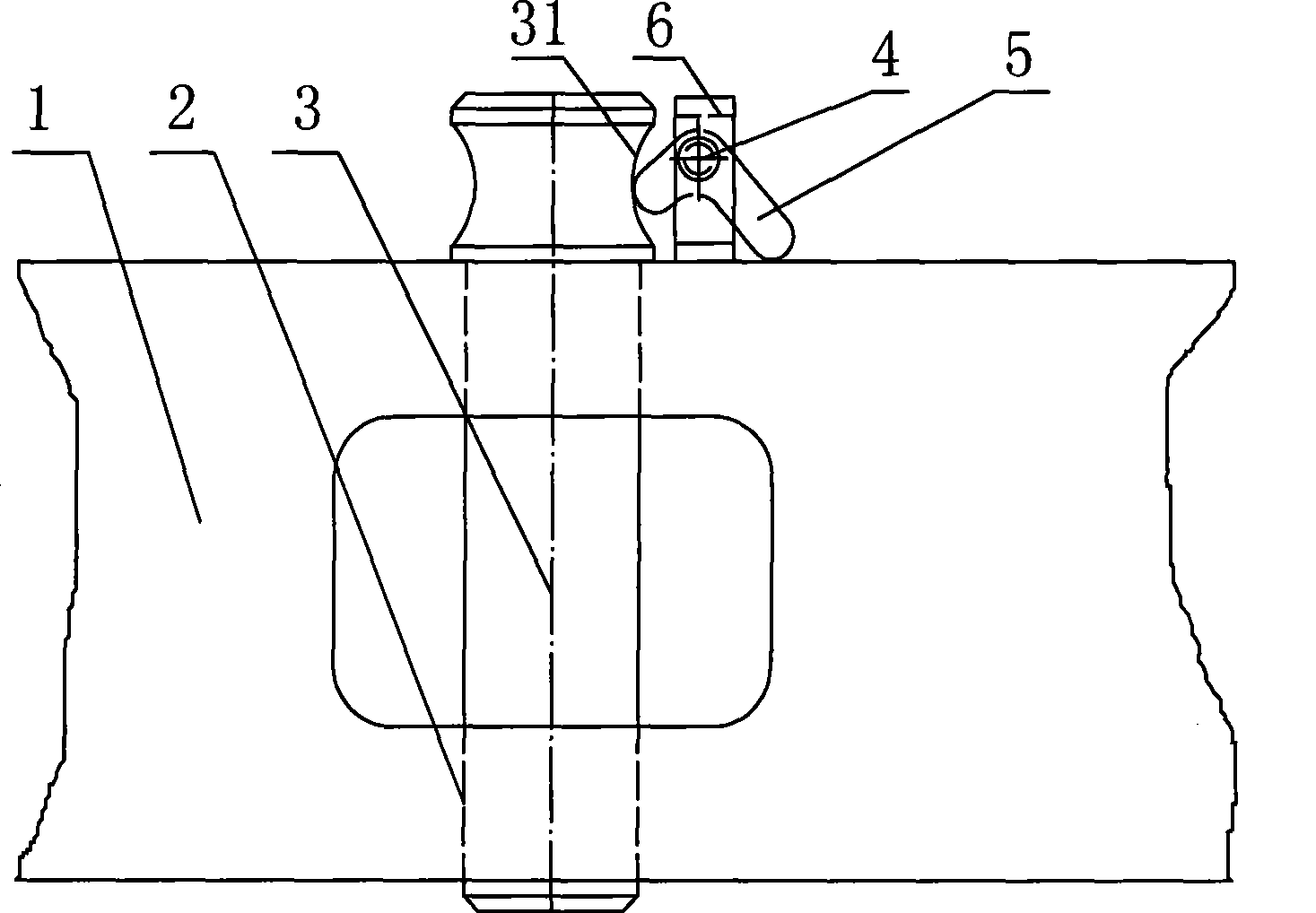
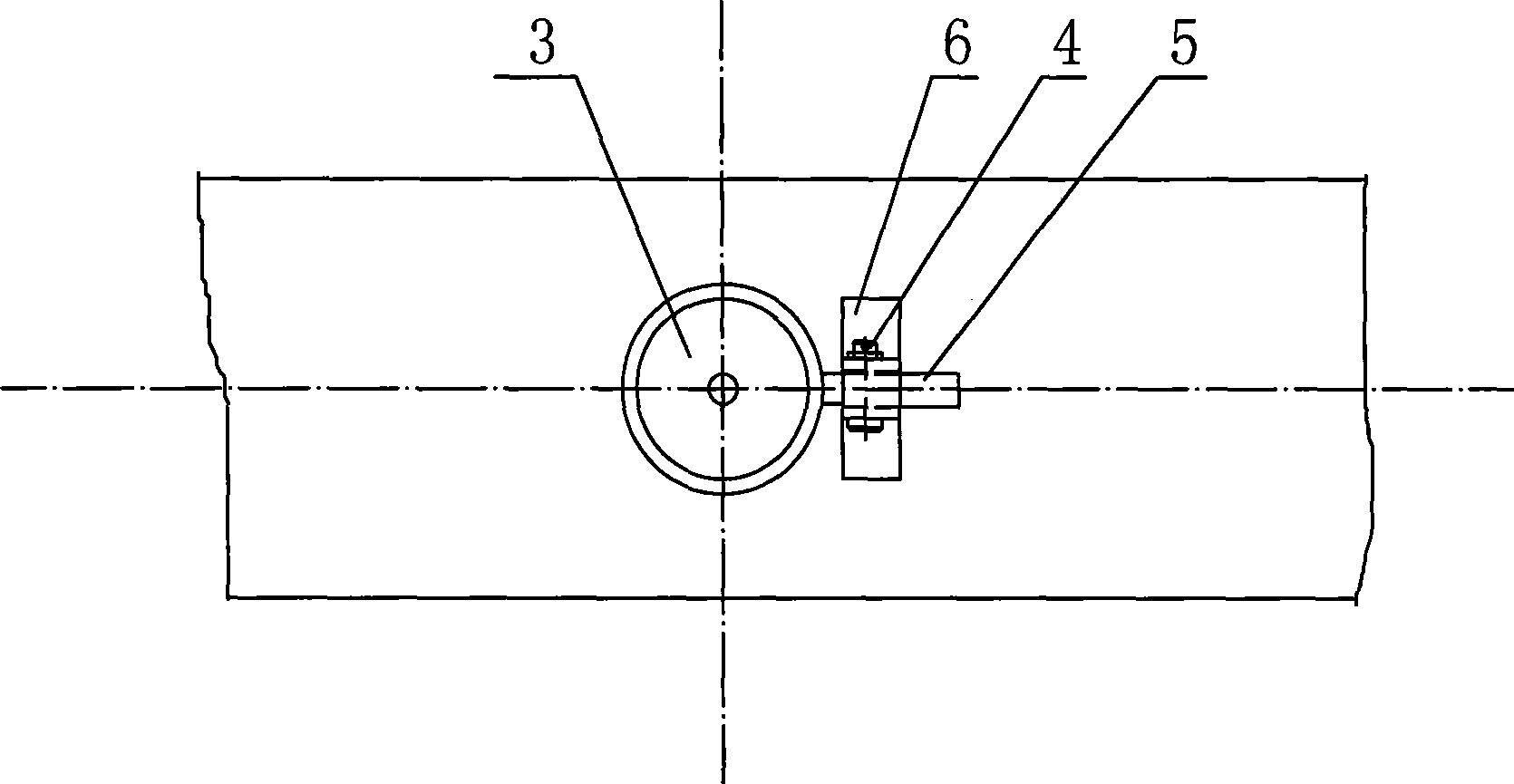
[0017] A kind of pin stop mechanism of axial limit of the present invention such as figure 1 , figure 2 As shown, a vertical pin hole 2 is provided on the shaft pin seat 1, and the shaft pin 3 is inserted in the pin hole 2. There is a clearance fit between the shaft pin 3 and the pin hole 2, which is used to connect the two components together. . The upper end of axle pin 3 is provided with a thicker nose portion 32 (referring to Figure 4 ), to prevent the shaft pin 3 from falling from the pin hole 2, the protruding head 32 is provided with a ring-shaped groove 31, preferably the cross-sectional shape of the groove 31 is arc-shaped.

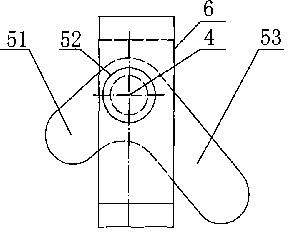
[0018] A support 6 is fixed near the pin hole 2 on the shaft pin seat 1 , a horizontal rotating shaft 4 is installed on the support 6 , and a rocking arm 5 is rotatably installed on the rotating shaft 4 . to combine image 3 The rocker arm 5 is provided with a locking portion 51, a rotating shaft hole 52 and a drooping portion 53, the locki...


PUM


Abstract

The present invention discloses an axial displacement-restricting backing pin mechanism, which comprises a shaft pin and a pin hole as well as a rocker and a rotating shaft which is horizontally arranged; wherein, the rocker is provided with a locking part, a rotating shaft hole and a drooping part; the locking part and the drooping part are respectively positioned on both sides of the shaft hole; the gravity center of the rocker is positioned on one side of the drooping part; the rotating shaft hole of the rocker can be rotationally assembled on the rotating shaft; the end of the shaft pin is provided with a groove; the drooping part of the rocker downwardly supports a fixed plane; the locking part of the rocker is just positioned in the groove of the shaft pin. The axial displacement-restricting backing pin mechanism can restrict the axial displacement of the shaft pin in order to ensure the normal connection position of the shaft pin, so that the shaft pin can be conveniently and quickly disassembled and assembled. Therefore the axial displacement-restricting backing pin mechanism is characterized by simple structure, convenient operation and reliable use.

Description

technical field [0001] The invention relates to a pin connection structure, in particular to a pin stop mechanism capable of limiting axial movement of a pin shaft. Background technique [0002] Pin shafts are widely used in mechanical structures, and the installation and positioning methods of pin shafts are also various. The common pin shaft axial limit methods include bolt-fixed, end clamp-fixed, cotter pin, etc. These structures are reliable, but disassembly and assembly are troublesome. For example, the traction pin of a vehicle needs to be disassembled frequently. Mechanisms are often inconvenient to use in such occasions that require quick installation. Contents of the invention [0003] The technical problem to be solved by the present invention is to provide a pin stop mechanism that facilitates quick disassembly and assembly of the shaft pin. [0004] In order to solve the above-mentioned technical problems, the present invention adopts the following technical ...

Claims


Application Information

Patent Timeline
Patent Type & Authority Patents(China)
IPC IPC(8): F16B21/14
Inventor 耿会良任中立郑峰
Owner MCC BAOSTEEL TECH SERVICE
Why Eureka
Try Eureka