
Adhesive patch

A patch and lamination technology, applied in medical science, dressing, sheet conveying, etc., can solve the problems of unsanitary paste, transfer of medicinal components, unsatisfactory, etc., and achieve the effect of easy peeling and sticking

Inactive Publication Date: 2009-01-21
TEIKOKU SEIYAKU KK TEIKOKU SEIYAKU CO LTD
View PDF1 Cites 5 Cited by
  • Summary
  • Abstract
  • Description
  • Claims
  • Application Information

AI Technical Summary

Problems solved by technology

[0014] (5) Furthermore, since the fingertips directly touch the paste, the paste becomes unhygienic, and care must be taken when attaching it to the damaged skin, so it is not ideal
[0015] (6) Also, since the fingertips are in direct contact with the paste, there is a possibility that the medicinal ingredients contained in the paste may transfer to the fingertips

Method used


Image

  • Adhesive patch
  • Adhesive patch
  • Adhesive patch

Examples


Embodiment

[0054] The present invention will be described below through several implementation modes constituting specific embodiments with reference to the accompanying drawings.

Embodiment approach 1

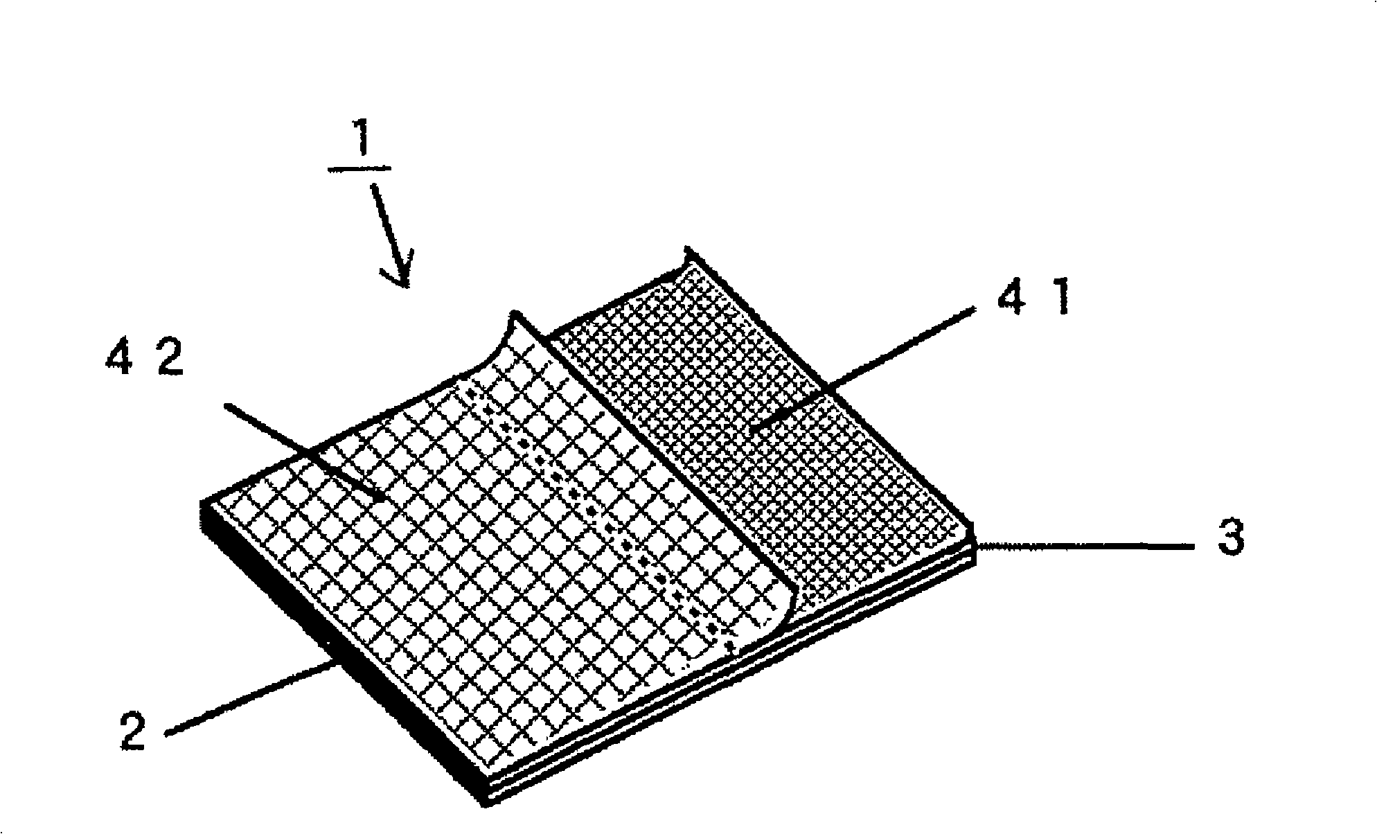
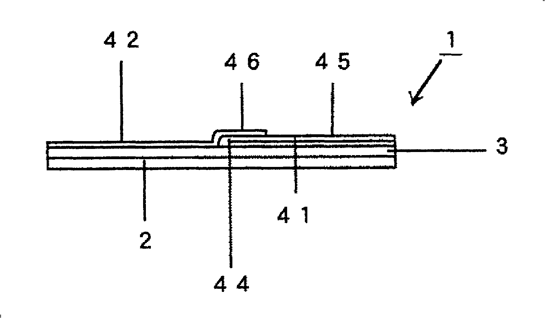
Fig. 1 shows patch preparations such as cataplasms in Embodiment 1 as an example of the present invention. Figure 1.1 for its stereogram, Figure 1.2 for side view.

[0056] The patch cataplasm 1 in the embodiment shown in FIG. The basic structure of the laminate of the two release films 41 and 42 on the paste surface of the paste 3.

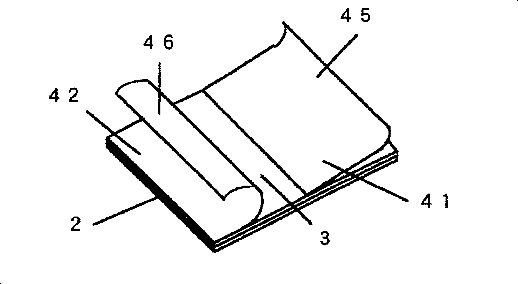
[0057] Among the two peeling films bonded on the plaster 3 surface of the patch 1, the first peeling film 41 located on the lower side is configured in such a way that it has a V-shaped peeling film shape bent at its central part. One side of the bent V-shaped first peeling film 41 is pasted from the end of the above-mentioned plaster face, with the bent portion 44 facing the center of the plaster, and the other side of the V-shaped peeling film is used as the pinching portion 45 .

[0058] On the other hand, among the two peeling films attached to the plaster surface, the second peeling film 42 positioned on the upper side thereof is constitu...

Embodiment approach 2

[0069] In this embodiment, the composition of the cataplasm 1 is the same as that of the previous embodiment, including a support 2, a paste 3 coated on the entire surface of the support 2, and a paste attached to the paste 3 as a laminate. Two stripping films 41,42 on the plaster face. In this embodiment, the two peeling films 41 and 42 are peeling films that siliconize polyethylene terephthalate sheets with a thickness of 25 to 38 μm and then emboss with a diamond pattern.

[0070] In addition, in the two peeling films bonded on the surface of the paste body 3, the cut surfaces at the ends of the nip portions 45 and 46 are corrugated.

[0071] The method for sticking the cataplasm 1 of the present embodiment to the affected part is the same as the method of the above-mentioned embodiment. In the present embodiment, the material of the two peeling films is a polyethylene terephthalate sheet, and its sheet thickness is 25mm. ~38 μm, higher hardness than the non-extended polyp...


PUM


Abstract

It is intended to provide an adhesive patch which can be safely and hygienically applied without touching an ointment in the course of from stripping a stripping film to applying the patch. Namely, an adhesive patch having a laminated structure comprising a support, a sticky ointment spread on almost the entire face of the support and a stripping film adhered to the ointment face, characterized in that: (a) The stripping film adhered to the ointment face consists of two stripping films; (b) the first stripping film is a V-shaped stripping film which is folded at the center and one face of the thus folded V-shaped stripping film is adhered from the edge of the ointment face so that the folded part face the center of the ointment while the other face of the V-shaped stripping film is employed as a knob; and (c) the second stripping film is adhered to the remainder of the ointment face and a laminated part is provided so that the edge of the second stripping film covers the folded part of the first V-shaped stripping film, thereby employing the laminated part as a knob.

Description

technical field [0001] The present invention relates to a patch such as a cataplasm for the purpose of reducing inflammation, relieving pain, or treating itching. More specifically, it relates to an excellent patch that can easily carry out a process from peeling off the peeling film to sticking the patch, not only for healthy people but also for elderly people or patients with poor grip strength. A series of operations, and the hands do not touch the paste at all, which can be applied safely and hygienically. Background technique [0002] Currently, cataplasms and the like having anti-inflammatory and analgesic effects are widely used as symptomatic treatments for low back pain, arthralgia, stiff shoulders, etc. caused by aging, labor, etc. In addition, in recent years, patches have been widely used in the treatment of herpes zoster and the like. [0003] Conventional patches 1 such as cataplasms, for example, as shown in FIG. It is constituted by a laminated structure c...

Claims


Application Information

Patent Timeline
Patent Type & Authority Applications(China)
IPC IPC(8): A61F13/02A61K9/70
CPCA61K9/703A61F13/023A61F2013/00817A61K9/7038A61F13/02A61K9/70
Inventor 植松正则
Owner TEIKOKU SEIYAKU KK TEIKOKU SEIYAKU CO LTD
Learn More