Squeezed profile to support lighting

a technology of squeezed profile and light source, which is applied in the direction of fixed installation, lighting and heating apparatus, lighting support devices, etc., can solve the problems of meeting technical challenges, achieve low cost and/or late-stage configurable modular luminaires, improve standardization/a mutual platform, and facilitate pinching

Active Publication Date: 2020-11-12
SIGNIFY HLDG BV
View PDF0 Cites 4 Cited by
  • Summary
  • Abstract
  • Description
  • Claims
  • Application Information

AI Technical Summary

Benefits of technology

[0030]Hence, the (monolithic) support element comprises a support part for supporting the lighting unit. The support part may include a face for configuring the lighting unit or a plurality of lighting units. The support part may also include a plurality of faces for configuring a plurality of lighting units. With the method as described herein (see also below), it is relatively easy to customize the length, the width, an angle relative to the duct, etc. This may allow a large freedom in terms of one or more of scaling and tailoring to the specific application position. For instance, by choosing the angle also the direction of the optical axis of the lighting unit may be chosen.
[0063]As indicated above, when creating the support part, also a transition part may be created. In further embodiments, the method may comprise creating a cable transit in the transition part, guiding an electrical cable through the cable transit, wherein the electrical cable is functionally coupled to the lighting system. For instance, during a pinching stage or after a pinching stage, such cable transit may be created. In embodiments, a pinching apparatus may be applied that is configured to pinch the starting duct and configured to create the cable transit in the transition part. As indicated above, especially the starting duct comprises a metal. Suitable metals, such as aluminum, may relatively easily be pinched. However, also plastics as support material may be used.
[0064]Further, the lighting device is functionally coupled with electronics. The term “electronics” may amongst others refer to one or more of a ballast, an electrical power device, a control system, etc., especially at least one or more of a ballast and an electrical power device. An excellent position for the electronics is in the remainder of the starting duct, i.e. the first duct. Therefore, the method further comprises introducing electronics in at least part of the remainder of the starting duct, and functionally coupling the electronics with the lighting unit. In this way an easy-to-install, low cost and / or late-stage configurable modular luminaire is obtained. The reason is that the lighting system can be functionally (mechanically and / or electrically) coupled to a pole of e.g. a luminaire e.g. a streetlight luminaire / fixture. Further, the obtained effect is improved standardization / an improved mutual platform. The reason is that a mutual platform for different types of luminaires such as for example street lighting products is obtained, because the (monolithic) support element comprises the electronics. Suggested configuration also enables that the electronics are arranged at a short distance to the lighting unit preventing / reducing issues with respect to safety and / or reliability. In embodiments, the electronics may be available before the support part is created. Then, after creating the support part, the functional coupling may be realized. In other embodiments, the electronics are introduced in the first duct after the support part is created. After creating the support part, also the functional coupling may be realized.

Problems solved by technology

It especially appears that with a frame-based luminaire different designs are possible but in the same time technical challenges may be met.

Method used


Image

  • Squeezed profile to support lighting
  • Squeezed profile to support lighting
  • Squeezed profile to support lighting

Examples


Embodiment Construction

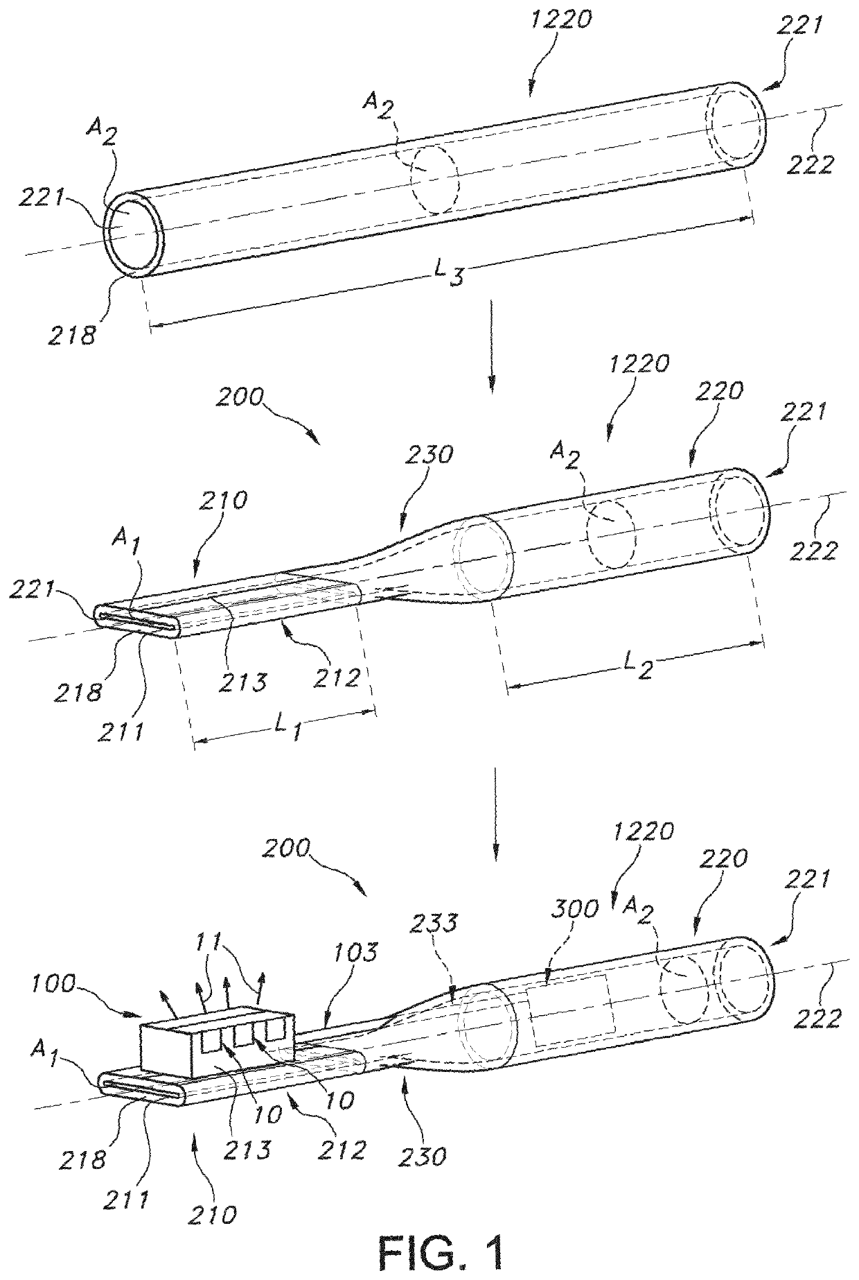
[0072]FIG. 1 schematically depicts an embodiment of a method of making a support element 200 and / or a lighting system 1. The method of making comprises providing a starting duct 1220 having a third length L3. The starting duct 1220 may be of metal. The term “starting duct” is applied, as a duct may be used to start with and transform into the support element 200 and lighting system, respectively. The starting duct is monolithic.

[0073]The starting duct 1220 comprises a duct channel 221 over at least part of the third length L3. This duct channel 221 has a second cross-sectional area A2.

[0074]To provide the support part, which may e.g. support a lighting unit 100, in embodiments the starting duct 1220 over part of the third length L3 together, until over part of the third length L3 the duct channel 221 has a cross-sectional area A1 in compliance with a ratio of the first cross-sectional area A1 to the second cross-sectional area A2 of 0≤A1 / A2≤0.8. In this way the support part 210 is p...


PUM


Abstract

The invention provides a lighting system (1) comprising a lighting unit (100) and a monolithic support element (200) for supporting the lighting unit (100), wherein the monolithic support element (200) comprises: —a support part (210) for supporting the lighting unit (100), wherein the support part (210) has a first length (L1), wherein the support part (210) has a support part outer shape and support part outer dimensions, wherein the support part (210) optionally includes a support part channel (211) over at least part of the first length (L1) having a first cross-sectional area (A1); —a first duct (220) having second length (L2), wherein the first duct (220) has a first duct outer shape and first duct outer dimensions, wherein the first duct (220) comprises a duct channel (221) over at least part of the second length (L2) having a second cross-sectional area (A2); —a transition part (230) bridging the support part (210) and the first duct (220); wherein one or mote of (i) the support part outer shape and the first duct outer shape differ, and (ii) the support part outer dimensions and the first duct outer dimensions differ.

Description

FIELD OF THE INVENTION[0001]The invention relates to a lighting system as well as to a method for making such lighting system. The invention also relates to a (monolithic) support element that can be used or made during such method.BACKGROUND OF THE INVENTION[0002]Street lamps, street poles, and street lamp fixtures are known in the art. US20130088864, for instance, describes a modular angled light engine, comprising: a center portion comprising an interlocking feature to connect to a second modular angled light engine; and at least one housing coupled to the center portion, wherein the at least one housing comprises: a heat sink coupled to a first side of the at least one housing; at least one light emitting diode (LED) coupled to an interior volume of the at least one housing; and a lens covering the at least one LED and coupled to a second side of the at least one housing.[0003]US2012 / 040585 discloses a method of assembling an airtight LED light bulb which has the steps of: conne...

Claims


Application Information

Patent Timeline
Patent Type & Authority Applications(United States)
IPC IPC(8): F21K9/232F21S8/08
CPCF21K9/232F21V29/503F21Y2115/10F21W2131/103F21S8/085F21Y2107/30E04H12/00F21S8/08F21V19/001F21V21/10F21V21/108F21V23/003F21W2131/10F21Y2115/30
Inventor BUKKEMS, PETER JOHANNES MARTINUSFRIEDERICHS, WINAND HENDRIK ANNA MARIAVREHEN, JORIS JANRIJSKAMP, PETER
Owner SIGNIFY HLDG BV
Why Eureka
Try Eureka