Ball type measuring prism
A technology for measuring prisms and spheres, which is used in measuring devices, measuring point markers, instruments, etc., and can solve the problems such as the easy change of the position of the glass pyramid, the difficulty of adjusting the position of the installation surface, and the poor control of the consistency of the measuring prism. , to achieve the effect that is not easy to change
Inactive Publication Date: 2010-12-01
CHENGDU JINGWEI TECHNOLOGICAL APP
View PDF1 Cites 0 Cited by
- Summary
- Abstract
- Description
- Claims
- Application Information
AI Technical Summary
Problems solved by technology
The disadvantage is that it is difficult to adjust the position of the mounting surface, the position of the glass pyramid fixed by silica gel is easy to change again, and the consistency of each spherical measuring prism after batch processing is not easy to control
Method used
View moreImage
Smart ImageViewing Examples
Examples
Embodiment Construction
Login to View More PUM
 Abstract
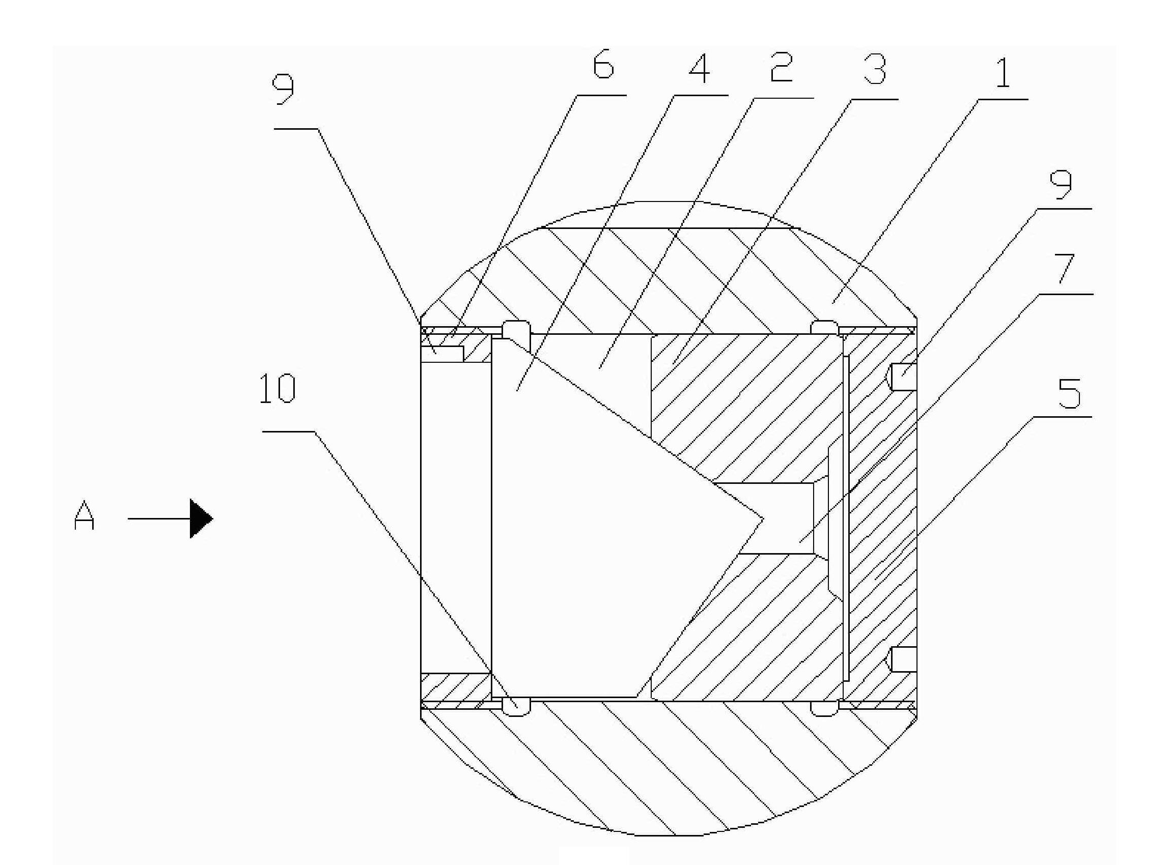
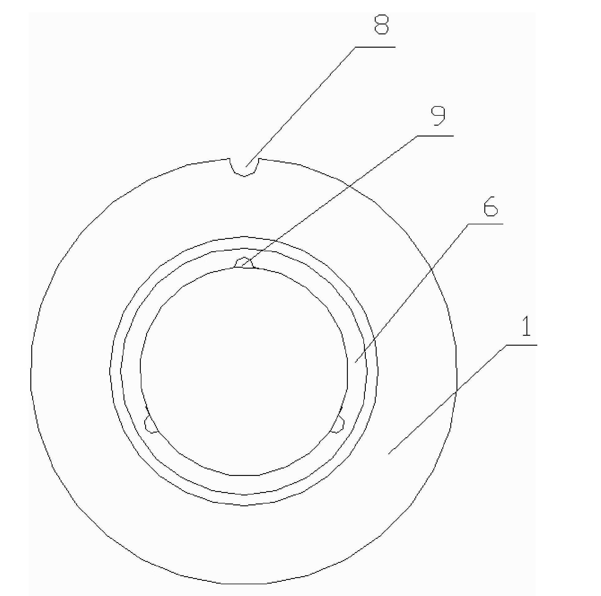
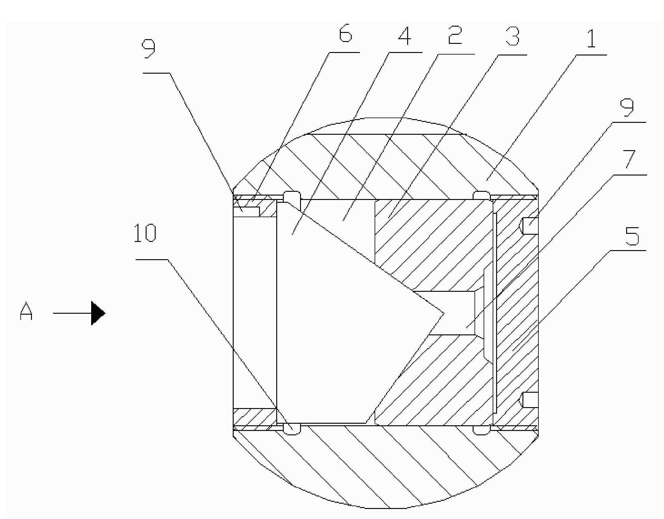
The invention provides a spherical measuring prism with convenient adjustment and difficult-changed position of a glass pyramid. The spherical measuring prism comprises a sphere. A through hole penetrating through the sphere is opened on the sphere and the ball center of the sphere is on the axle wire of the through hole. The through hole is internally provided with a rear cover, a positioning corner, the glass pyramid and a front cover. The rear cover is installed in the through hole of the sphere and the glass pyramid is installed on the positioning corner while the front cover is installedin the through hole. The spherical measuring prism of the invention can drive the glass pyramid to move backwards by installing the front cover so as to ensure that three mutually vertical surfaces on the glass pyramid are closely contacted with the positioning corner, and accurately cause the superposition of the reflection center of the glass pyramid and the ball center of the sphere by controlling the working accuracy of components and back and forth adjustment when in installation, therefore, the position of the glass pyramid after installation is not easy to change.
Description
Spherical Measuring Prisms technical field The invention relates to a measuring prism, in particular to a spherical measuring prism. Background technique In the field of surveying and mapping, the three-dimensional coordinates of the measuring prism can be obtained through the measurement of the measuring prism by the total station, so that the spatial position of the measured object can be indirectly reflected according to the fixed relationship between the placement position of the measuring prism and the measured object. Therefore, the accuracy of the measuring prism directly affects the final measurement accuracy. The measuring prism is a glass pyramid with 3 mutually perpendicular faces and 1 cutting face, and the 3 mutually perpendicular faces intersect to form a pyramid. The three mutually perpendicular surfaces are surface-treated with a mirror-making process, so that the interior becomes a reflective mirror surface, so that no matter what angle the incident ligh...
Claims
Login to View More Application Information
Patent Timeline
 Patent Type & Authority Patents(China)
IPC IPC(8): G01B11/00G01C15/02
Inventor 陈心一姚云峰周敬勇唐杰彭兵杜鹃杨娱罗也王立德
Owner CHENGDU JINGWEI TECHNOLOGICAL APP
Features
- R&D
- Intellectual Property
- Life Sciences
- Materials
- Tech Scout
- Unparalleled Data Quality
- Higher Quality Content
- 60% Fewer Hallucinations
Learn More Browse by: Latest US Patents, China's latest patents, Technical Efficacy Thesaurus, Application Domain, Technology Topic, Popular Technical Reports.
© 2025 PatSnap. All rights reserved.Legal|Privacy policy|Modern Slavery Act Transparency Statement|Sitemap|About US| Contact US: help@patsnap.com


