Residual current device for an electric circuit breaker

A residual current and circuit breaker technology, applied to circuit breaker components, emergency protection devices, switch terminals/connections, etc., can solve problems such as difficult and difficult assembly

Active Publication Date: 2009-01-28
BTICINO
View PDF4 Cites 8 Cited by
  • Summary
  • Abstract
  • Description
  • Claims
  • Application Information

AI Technical Summary

Problems solved by technology

However, assembly is not easy and

Method used


Image

  • Residual current device for an electric circuit breaker
  • Residual current device for an electric circuit breaker
  • Residual current device for an electric circuit breaker

Examples


Embodiment Construction

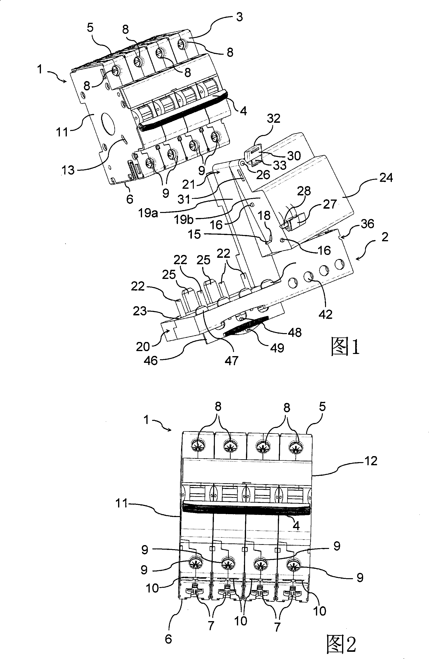
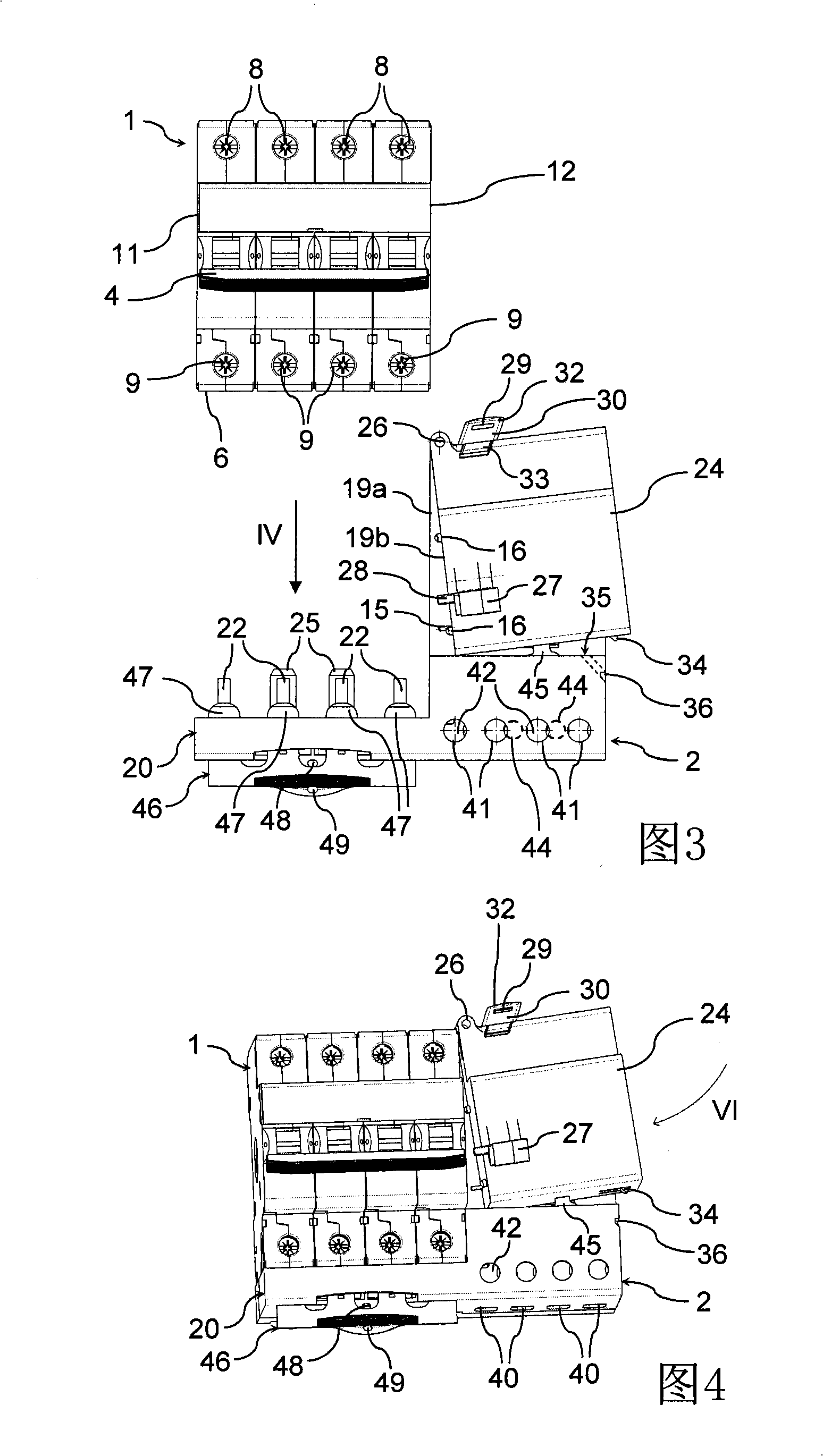
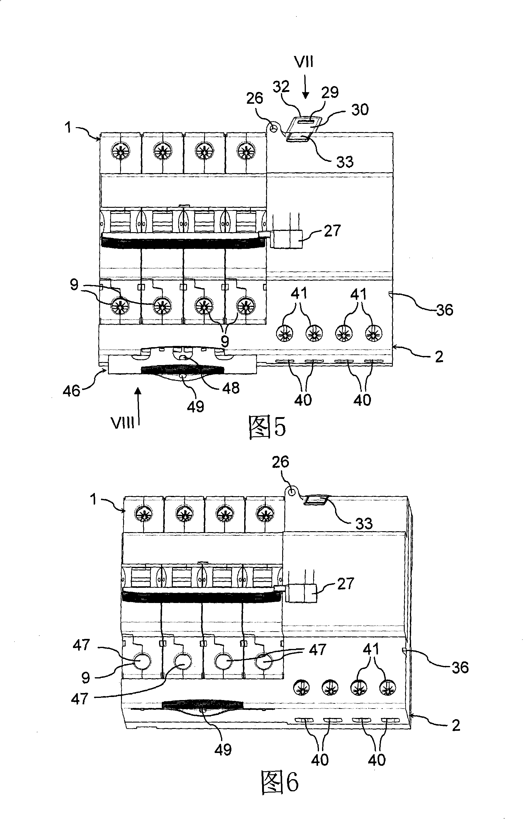
[0023] Referring to FIG. 1 , a residual current device connectable to a circuit breaker 1 is generally designated 2 . Preferably, the circuit breaker 1 is a multipole circuit breaker, which can be fixed to a DIN rail and, in the example described here, is a magneto-thermal quadrupole circuit breaker in a non-limiting manner, which A magnetothermal four-pole circuit breaker is formed, for example, by juxtaposing four DIN single-pole modules. In a known manner, in a four-pole circuit breaker 1 four DIN single-pole modules have kinematic actuators interconnected by mechanical connecting elements.

[0024] The circuit breaker 1 has a body approximately in the shape of a parallelepiped. Protruding from the front face 3 of the circuit breaker body 1 is a pivoting drive rod 4 provided for operating the circuit breaker 1 . In the example shown here, the drive rod 4 is embodied as a rod of C-section, engaging the four drive rods of a DIN monopolar module in order to be able to manipu...


PUM


Abstract

The residual current device (2; 200) associable to an electric circuit-breaker (1), the residual current device (2;200) comprising: interconnection electric terminals (22) suitable to establish, by co-operating with respective electric terminals of the circuit-breaker (1) that are accessible through a first face (6) of the latter, an electrical connection between the device (2;200) and the electric circuit-breaker (1); and mechanical coupling means (15,16) suitable to allow a mechanical interaction between the device (2;200) and the circuit-breaker (1) through a second face (12) perpendicular to said first face (6). The device (2;200) comprises first (20,21;221) and second (24;220) parts, which are pivotally connected to each other and carry said interconnection electric terminals (22) and said mechanical coupling means (15,16), respectively.

Description

technical field [0001] The invention relates to the technical field of equipment for distributing and controlling electric power, in particular to a residual current device that can be connected with a circuit breaker. Background technique [0002] As is well known, a residual current device is an electronic device that includes a totalizer transformer and a trip device that is electrically connected to the secondary coil of the transformer to mechanically Leave the connected circuit breaker open. [0003] According to the fact that it has been widely used for a long time, residual current devices and circuit breakers are manufactured as separate modular units for subsequent assembly before installation, eg on construction sites or the like. This fact is advantageous to manufacturers, whereby they can avoid factory assembly and thus produce a small number of product types. Also, this situation allows the assembler to reduce the inventory of various parts. A residual curre...

Claims


Application Information

Patent Timeline
IPC IPC(8): H01H71/08H01H73/20H01H83/14
CPCH01H83/226H01H71/082
Inventor 巴塞焦·雷克里斯蒂安·韦基
Owner BTICINO
Why Eureka
Try Eureka