System, method and apparatus for implementing business continuity in household network circumstance

A home network and business continuity technology, applied in the home network field, can solve the problems of loss of program content, inability to better adapt to different applications and users, and inability to obtain user attributes and business context information correlation, etc., to achieve a good experience. Effect

Inactive Publication Date: 2009-01-28
HUAWEI TECH CO LTD
0 Cites 33 Cited by

AI-Extracted Technical Summary

Problems solved by technology

[0019] 1. When watching live programs, the above switching process will cause loss of program content;
[0020] 2. Since there is no relevant processing for user attributes (Profile), the association between user attributes and business context inform...

Method used

[0066] The embodiments of the present invention aim at the home network environment, provide automatic switching and use of service functions among multiple devices in the home network environm...

Abstract

The embodiment of the invention discloses a system for realizing service continuity in a home network environment, which comprises a service providing unit, a digital media controller, a first digital media presenter and a second digital media presenter. The service providing unit is used to provide the first digital media presenter with service data, receive data of services which is to be continued and is controlled to be cached by the digital media controller, and provide the second digital media presenter with the data of the services to be continued. The embodiment of the invention also discloses a method for realizing the service continuity in the home network environment, the digital media controller, gateway equipment, a digital media server, a digital media presenter and a service continuity function server. After the system is applied, the missing of the content of programs during the switching process can be avoided, the continuous use of live broadcast and on-demand broadcast services in the home network environment can be realized, and users can obtain better experience from the services.

Application Domain

Technology Topic

Image

  • System, method and apparatus for implementing business continuity in household network circumstance
  • System, method and apparatus for implementing business continuity in household network circumstance
  • System, method and apparatus for implementing business continuity in household network circumstance

Examples

  • Experimental program(1)

Example Embodiment

[0064] In order to make the objectives, technical solutions and advantages of the present invention more clearly expressed, the present invention will be further described in detail below with reference to the accompanying drawings and specific embodiments.
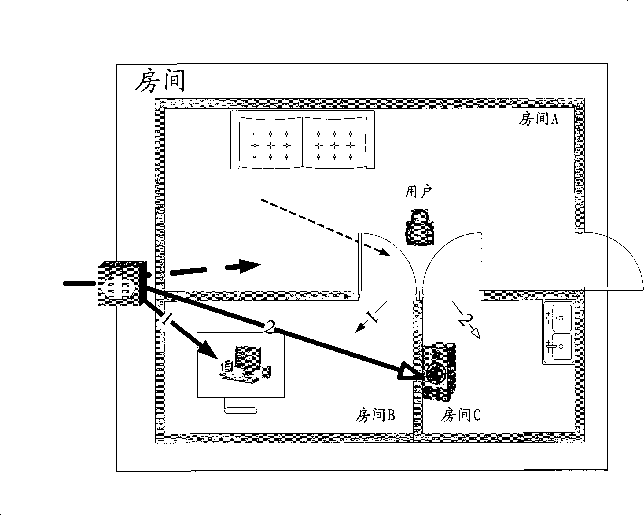
[0065] First, explain the concept of business continuity. The continuous use of services among multiple devices refers to continuous consumption services for users. What users need is business continuity (delay, jitter, etc. within the tolerable range), and do not care about changes in the underlying conversation. At the service session level, switching between devices will inevitably lead to changes in certain session participating entities, paths, etc., and the original sessions that have undergone these changes will end, and related new sessions will also be generated.
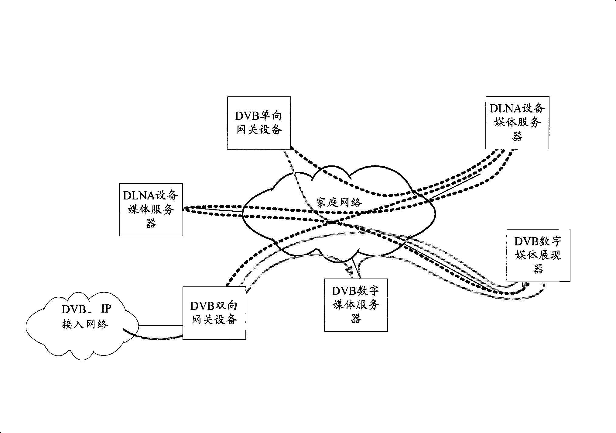
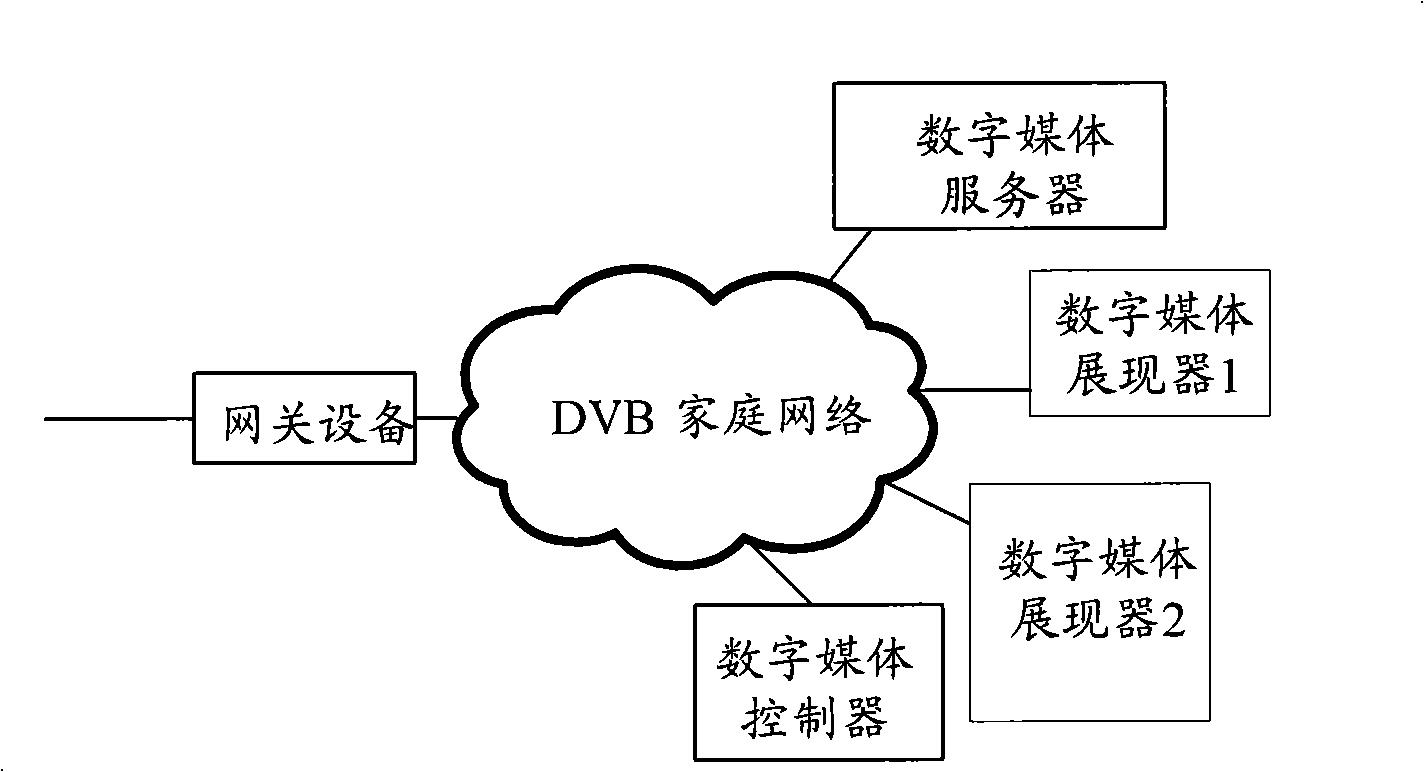
[0066] The embodiment of the present invention is aimed at a home network environment, provides automatic switching of service functions among multiple devices in the home network environment, and can reproduce the characteristics of service usage (such as application context continuation, user profile information) Matching) to provide better support for the continuous use of seamless business.
[0067] The use of services from service publishers to consumer customers involves the service end, core network, access network and home network. The embodiment of the present invention realizes the continuity of service connection in the home network environment, and the supported services include live broadcast LMB, VoD on demand, etc.
[0068] The services deployed by the service publisher outside the home network are external services. Internal services are services that are deployed inside the home network, such as watching DVD programs through a DVD player. The service usage mode is mainly as follows: other home network devices other than the gateway device GD do not directly invoke external services, and the gateway device is responsible for converting the external services into internal services of the home network. The gateway device has the following functions: acquisition, conversion and internal release of business metadata; acquisition, format matching, conversion, and release of business data; management of internal and external business sessions, etc.
[0069] The business of internal equipment use is mainly provided by DMS/GD. DMS provides VoD services, GD converts various external services (such as VoD/LMB, etc.) to the home network.
[0070] The current DVB-HN equipment (DVB-UGD, DVB-BGD, DVB-DMC) plays an important supporting role in the technical solution for achieving seamless service use.
[0071] image 3 It is a schematic diagram of a system structure of a home network environment in an embodiment of the present invention.
[0072] The services supported by the embodiment of the present invention include live LMB and VoD on demand, and so on.
[0073] Such as image 3 As shown, the gateway device is responsible for converting external services into home network internal services, and has the following functions: acquiring business metadata, converting business metadata into a format supported by HN, and publishing the converted business metadata to HN; Business data acquisition, format matching, conversion, and release; management of internal and external business sessions, etc. Home network devices other than the gateway device (GD) do not directly invoke external services.
[0074] The services that can be used by the internal devices of the DVB home network (DVB-HN) are mainly provided by the digital media server (DMS) and/or GD. DMS provides VoD services, and GD converts various external services (VoD/LMB, etc.) into the home network.
[0075] It can be found that the functions currently defined for DVB-GD/DMC are relatively basic, and there is no public interoperability interface defined. These status quo make them insufficient to support the continuous use of services. A feasible solution is to expand and define their own correspondence based on them. equipment.
[0076] in image 3 The main equipment functions in the system are as follows:
[0077] Gateway device (Gateway Device, GD), used to connect the home network and the external access network, and convert the external business to the internal use of the home network;
[0078] Digital Media Server (DMS) is a device that provides internal services for the home network, such as VCR/PC.
[0079] Digital Media Render (DMR): A service consumer device that receives and displays content from DMS/and/or GD, such as television (TV) and stereo (stereo).
[0080] Digital Media Controller (DMC): used to discover and control DMS and/or GD and DMR, and control the business consumption process.
[0081] Figure 4 It is a schematic diagram of a system structure for realizing business continuity according to an embodiment of the present invention. in Figure 4 , The business needs to be switched from the first digital media presenter (DMR1) to the second digital media presenter (DMR2).
[0082] The service providing unit is configured to provide service data to the first digital media presenter in the home network, accept the control of the digital media controller to buffer the pending service data, and provide the second digital media presenter with the pending service data;
[0083] The digital media controller is used to collect real-time service information from the first digital media presenter to construct application context information, send the application context information to the Service Continuity Function Server; and indicate when the service switch is triggered The service providing unit caches the pending service data, obtains user description and application context information from the service continuity function server, and instructs the service provider to display the pending service data on the first digital media presenter according to the user description and application context information;
[0084] The first digital media presenter is used to display business data and provide real-time business information to the digital media controller;
[0085] The second digital media presenter is used to display the pending service data;
[0086] The business continuity function server is used to store user description and application context information, and provide the user description and application context information to the digital media controller.
[0087] Specifically, the service providing unit can be either a gateway device (GD) or a digital media server. When the service providing unit is specifically a gateway device, the gateway device connects the home network and the external access network, converts the external service to the internal use of the home network, and sends it to the digital media presenter (including the first digital media presenter) under the control of the digital media controller. (And the second digital media presenter) provide services, cache data of pending services, etc. When the service providing unit is specifically a digital media server, the digital media server, under the control of the digital media controller, provides the digital media presenter (including the first digital media presenter and the second digital media presenter) with internal services of the home network, such as DVD Business etc.
[0088] The digital media controller is a control device used to interact with users. It is responsible for discovering and controlling various devices in the home, controlling the business consumption process (such as setting, pause, fast forward, etc.), and controlling various related to business continuity functions Data (such as user description, application context information, etc.) management, and automatic processing of business continuity based on the aforementioned data.
[0089] The business continuity function server, as a central storage device, is used to centrally manage various data related to the business continuity function (such as user description, application context information, etc.) under the control of the digital media controller.
[0090] Each entity in the above system follows the DVB-HN definition and has been enhanced in function. Such as Figure 4 The devices in the device use non-UPnP (out-of band") communication protocols to transmit out-of-band content (content data of the business). These device divisions are logically, and the actual physical device may have multiple logical device types ability.
[0091] In order to support the continuous functions of live and on-demand services, the embodiment of the present invention proposes a new service continuity function server to be responsible for the centralized management of service continuity function (SCF) information. The following is a more detailed description of the business continuity function server.
[0092] The business continuity function server (SCF-Server) is a logical device that serves as the central storage of the business continuity function, which centrally controls and manages various data related to the business continuity function, such as user descriptions and pending business information. SCF-Server is responsible for providing storage, publishing, and query functions for these data.
[0093]When implemented, the SCF-Server can exist as a device alone, or it can be deployed together with a gateway or DMS on a physical device. The business continuity function server can also be used to directly receive input for the user description and save the user description.
[0094] The digital media controller can be used to accept user operations to trigger service switching. Figure 4 The illustrated embodiment may further include an environment awareness system, which is used to detect changes in the user's geographic location and trigger service switching.
[0095] The digital media controller may be further used to collect user descriptions and send the user descriptions to the business continuity function server.
[0096] The interaction between the various device entities in the above system follows the definition of DVB-HN, and the related calling interface is enhanced. The interaction interface is described as follows:
[0097] DMC controls the interface of DMR (that is Figure 4 Interface 1): including selecting the target display device DMR, obtaining and configuring the protocol/format supported by the DMR, controlling the display characteristics of the DMR, and coordinating and managing the operation of the DMR according to the user's control (play, stop, pause), DMR Send event notifications to DMC to inform changes of internal status, etc.) and service continuity enhancement interface (configure DMR enhancement parameters).
[0098] The interface of the DMC control service providing unit (that is, Figure 4 The interface in 2) can be divided into:
[0099] DMC controls the DMS interface: including locating and selecting the desired content on the DMS, coordinating and managing the operation of the DMS according to the user's control (play, stop, pause), DMS sending event notifications to the DMC to inform internal status changes, etc.) and Service continuity enhancement interface (restoration of application context, optional support interface for audio and video part switching).
[0100] DMC controls the GD interface: including basic interface (calling interface for DVB-GD defined functions) and business continuity enhancement interface (session management interface, calling interface for business data cache, restore application context, optional audio and video part Switching support interface).
[0101] The interface between DMC and SCF-Server (that is Figure 4 Interface 3): Provides storage, release, and query of information about pending services, application context, and user descriptions.
[0102] The key data involved in the embodiment of the present invention includes:
[0103] Business information: including business description, metadata, etc.; application context information: including the use of the business, including real-time application status (such as mute), language, business use time, business use history list, etc.; user description: including specific The record of user data describes the attributes and preferences of the user, and may include language settings, sound effects, shortcut key settings, bookmarks, etc.
[0104] The service information used in the embodiment of the present invention follows Universal Plug and Play Content Discovery Service (UPnP CDS) and Service Discovery and Selection (SD&S)/Broadband Content Wizard (Broadband). Content Guide, BCG) form. The service information of the pending service can be described and managed in UPnP CDS.
[0105] Although specific implementation forms are listed above for business information, those skilled in the art can realize that the present invention is not limited to UPnP CDS and SD&S/BCG forms.
[0106] Figure 5 It is a schematic diagram of the structure of a business continuity function server according to an embodiment of the present invention. Such as Figure 5 As shown, the business continuity function server includes:
[0107] The data management module 502 is used to save user description and application context information, and the application context information is provided by the digital media controller;
[0108] The pending service management module 502 is used to store pending service information and provide a pending service list to the digital media controller for the digital media controller to select pending services.
[0109] Specifically, the pending service management module 501 can be used to store, publish, and query information related to pending services, including a list of pending services in the home network environment and service information of each pending service;
[0110] The data management module 502 is used to provide management of key data used in the business continuity function, which specifically includes application context management and user description management.
[0111] Application context management: Responsible for providing the functions of publishing, querying, and updating application context data for each pending business; User description management: Responsible for publishing, querying, and updating user description data.
[0112] Figure 6 It is a schematic diagram of an exemplary structure of a gateway device (GD) according to an embodiment of the present invention.
[0113] The session management module 602 is used to manage business-related sessions between the home network and the external access network;
[0114] The service management module 603 is configured to accept the control of the digital media controller to buffer the pending service data, and provide the pending service data to the switched digital media presenter;
[0115] The application recovery module 604 is configured to control the service providing unit to display the pending service data on the digital media presenter to which the service control is switched according to the user description and the application context information.
[0116] The following specifically describes the sub-function modules of the GD device:
[0117] DVB-GD function module 601. For the function definition of DVB-HN gateway equipment, please refer to the relevant definition of DVB-HN. It has: content publishing, including metadata conversion (such as the conversion of business information between UPnPCDS and DVB SD&S/BCG); Delivery; dynamic selection of service components; quality of service (QoS) management; two-way gateway BGD has additional functions of access network server control and remote management.
[0118] Session management module 602: Responsible for managing and maintaining business-related sessions, including creating new sessions, maintaining the correspondence between sessions inside and outside the gateway, and converting/forwarding related session information.
[0119] For example, DVB-HN uses Real Time Streaming Protocol (RTSP) and Real-time Transport Protocol (RTP), and Digital Living Network Alliance (DLNA) uses Hypertext Transfer Protocol (HypertextTransfer). Protocol, HTTP) as the protocol for transmission and session (RTP is optional), this module needs to complete the conversion and maintenance of the session between RTSP and HTTP.
[0120] Business management module 603: Responsible for the management of business data, mainly buffering and sending LMB business data. In order to support the lossless reproduction of the content of the LMB service during handover, the service management service needs to have a time shift function.
[0121] The gateway device may also include a media stream management module 605 that is optional for the service providing device.
[0122] Among them, the interface between each sub-module is described as follows.
[0123] DVB-GD function module 601 and session management module 602: The session management module 602 calls the metadata conversion function of the DVB-GD function module 601, and the DVB-GD function module 601 calls or triggers the session management function of the session management module 602.
[0124] Media stream management module 605 and session management module 602: When the media stream management module 605 processes the original stream session and the newly split media stream session, it needs to call the session management function of the session management module 602 to control the original stream session.
[0125] Media stream management module 605 and DVB-GD function module 601: The media stream management module 605 needs to obtain the content of the original stream from the DVB-GD function module 601.
[0126] Media stream management module 605 and application recovery module 604: The application recovery module 604 notifies the media stream management module 605 to recover the application context information of a certain media stream.
[0127] The application recovery module 604 includes a service leaving function module and a service continuing function module.
[0128] The business leaving function module is the main entry module for the end user to use the business continuity system. The module receives the end user's command (such as a click on the UI provided by the DMC) or is triggered by the environment sensing system, and automatically handles the subsequent control process of the business leaving; The business continuation function module receives the end user's request or is triggered by the environment awareness system, and automatically processes the processing of the continued business stage of the pending business. The end user can continue to consume the previous business and obtain the same business status and user experience.
[0129] The DMC equipment will be introduced below:
[0130] DMC equipment is based on DVB-DMC equipment. In order to support business continuity functions, the SCF control function module SCF-C is newly expanded. SCF-C provides interactive control and related data (application context, user description) management functions.
[0131] Figure 7 It is an exemplary structure diagram of a DMC according to an embodiment of the present invention. Such as Figure 7 Shown:
[0132] The DMC device includes a DVB-DMC function module 701, a service leaving function module 702, and a service continuing function module 703.
[0133] DVB-DMC function module 701. Refer to DVB-HN related definitions for the function definition of DVB-DMC equipment, including: content discovery; display device selection; connection establishment/closing; flow control; flow monitoring.
[0134] The business leaving function module 702 is used to collect real-time business information from the digital media presenter to construct application context information, and send the application context information to the business continuity function server;
[0135] The service continuation function module 703 is used to control the service provision unit to cache pending service data when the service switch is triggered, obtain user description and application context information from the service continuity function server, and control service provision according to the user description and application context information The unit displays the pending service data on the digital media presenter to which the service control is switched
[0136]The business leaving function module 702 is the main entry module for the end user to use the business continuity system. The module receives the end user's command (such as a click on the UI provided by the DMC) or is triggered by the environment sensing system, and automatically handles the subsequent control process of the business leaving . Service continuation function module 703: Receives the end user's request or is triggered by the environment awareness system, and automatically processes the processing of the service connection phase of the service to be resumed. The end user can continue to consume the previous service and obtain the same service status and user experience.
[0137] The business leaving function module 702 and the business continuing function module 703 provide the core control functions of the technical solution of the embodiment of the present invention. The function realization of these two modules mainly calls the GD device, the DMS device, the SCF-Server device and the DMR device to cooperate to complete the SCF function. .
[0138] The interface between each sub-module is described as follows.
[0139] DVB-DMC function module 701 and service leave function module 702: The service leave function module 702 calls the interface of the DVB-DMC function module 701 mainly including service selection and display equipment, connection management, adaptation protocol/format, and stream management.
[0140] DVB-DMC function module 701 and service continuation function module 703: The service continuation function module 703 calls the interface of the DVB-DMC function module 701, which mainly includes service selection and display equipment, connection management, adaptation protocol/format, and stream management.
[0141] As a service provision device, DMC can further include a media stream management module. The media stream management module is an optional additional function module for service providing equipment, and is responsible for the management and control of the media stream when the service content (audio, video) is partially switched.
[0142] When the service content (audio, video) is partially switched, it is divided into two situations according to different service control and transmission realization methods:
[0143] When the audio and video of the business content are transmitted as separate media streams, the media stream corresponding to the switched content needs to be separated from the original session, redirected to the new display device, and a new session will be established to manage the media stream. .
[0144] When the audio and video of the service content are mixed and transmitted in one stream, the audio and video need to be decoded separately, and then each packaged into a separate media stream for transmission, and each corresponding session control is established.
[0145] The media stream management module chooses whether to decode the service content and package it separately according to different service content provision methods, redirect the switched media stream to the new display device, establish a corresponding new session at the same time, and be responsible for multiple subsequent media streams Management of related sessions and synchronization of the status of corresponding sessions.
[0146] The application recovery module belongs to the module of the service providing device (GD, DMS), and is responsible for controlling the reproduction of the application context of the service published on the device. The main function of the application restoration module is to set the service on the service provider device according to the application context parameters provided by the DMC, so as to realize the restoration of the application context accordingly.
[0147] The DMS equipment will be described in detail below. DMS equipment is based on DVB-DMS equipment, Figure 8 It is a schematic structural diagram of a DMS according to an embodiment of the present invention.
[0148] Such as Figure 8 As shown, the DMS device includes a DVB-DMS function module 801 and an application recovery module 802.
[0149] The DVB-DMS module 801 is used to publish service data, accept the control of the digital media controller to buffer the pending service data, and provide the pending service data to the switched digital media presenter;
[0150] The application recovery module 802 is used to display the pending service data on the digital media presenter to which the service control is switched according to the user description and application context information sent by the digital media controller.
[0151] Specifically, the functions of the DVB-DMS function module 801 can be found in the function definition of DVB-DMS equipment (see DVB-HN related definitions), with functions: publishing content; delivering content; dynamically selecting service components; trick play (Trick) mode; Storage management; QoS monitoring.
[0152] The DMS device also includes an application recovery module 802 that is required by the service providing device. Refer to the above description for the function of the application recovery module 802, which is equivalent to Figure 6 The application recovery module 604 in.
[0153] Optionally, the DMS device may further include a media stream management module 803 of the service providing device. The media stream management module 803 is used to separate the media stream corresponding to the switched service data from the original session when the audio and video of the service data are transmitted as separate media streams, and redirect to the switched digital media presenter ; And when the audio and video of the service data are mixed and transmitted in one stream, the audio and video are decoded separately, and the decoded audio and video are respectively packaged into a separate media stream, and redirected to the digital media to be switched to Presenter.
[0154] The interface between each module in DMS equipment is explained as follows.
[0155] DVB-DMS function module 801 and media stream management module 803: The media stream management module 803 needs to obtain the content of the original stream from the DVB-DMS function module 801.
[0156] Application recovery module 802 and media stream management module 803: The application recovery module 802 notifies the media stream management module 803 to recover the application context information of a certain media stream.
[0157] Refer to the DLNA-DMS device, the DMS device is defined in the xmlserviceList of the UPnP MediaServer, and the following SCF-Recover service definition of the application recovery module is attached:
[0158]
[0159] DMR equipment is based on DVB-DMR equipment. In order to support business continuity functions, the equipment configuration module SCF-DMR is newly expanded. Picture 9 It is a schematic diagram of the DMR structure according to an embodiment of the present invention.
[0160] Such as Picture 9 As shown, the DMR includes a DVB-DMR function module 901 and a device configuration module 902.
[0161] The DVB-DMR function module 901 is used to display service data and provide real-time service information to the digital media controller. The digital media controller controls the digital media presenter to which the service control is switched to display the waiting information according to the user description and application context information. Continue business data;
[0162] The device configuration module 902 is used to set additional device parameters such as subtitle language, sound effects, and shortcut key settings of the digital media presenter, so as to implement additional settings for the digital media presenter.
[0163] Specifically, the DVB-DMR function module 901 has the function definition of DVB-DMC equipment (see DVB-HN related definitions), and has functions: playing content; publishing equipment capabilities; QoS reports; Trick mode support; providing Trick mode interfaces; presentation control .
[0164] The device configuration module 902 is a module provided by the presentation device, and is responsible for the additional settings of the DMR device (using DVB-DMR RCS service settings for some existing parameters of UPnP). The definition of the device configuration module 902 is mainly to set additional parameters for the SCF-DMR to implement additional settings for the display device.
[0165] The serviceList of the DMR device defined in the xml definition of UPnP MediaRender is additionally defined as follows, in which the service type (serviceType) and service ID (serviceId) fields are defined. The specific format of serviceList is as follows:
[0166]
[0167] The invention also provides a method for realizing business continuity in the home network environment. Picture 10 It is a schematic diagram of an exemplary process flow of a method for realizing business continuity in a home network environment according to an embodiment of the present invention.
[0168] Such as Picture 10 As shown, the method includes:
[0169] Step 1001: Collect real-time business information from the digital media presenter to construct application context information, and send the application context information to the business continuity function server;
[0170] Step 1002: When the service switching is triggered, the control service provider unit caches the pending service data, obtains the user description and application context information from the service continuity function server, and controls the service provider unit in the service control according to the user description and application context information. The switched to digital media presenter displays the pending business data.
[0171] Among them, the digital media controller may collect user descriptions and send the user descriptions to the business continuity function server. It is also possible that the business continuity function server directly receives the input for the user description, and saves the user description.
[0172] The user description includes any one or any combination of more than one of the following parameters: user attributes; user preferences; language settings; sound effects; shortcut key settings; bookmarks.
[0173] The application context information includes any one or any combination of more than one of the following parameters: real-time application status; language type; business use time; business use history list.
[0174] In addition, the service switching trigger may be the user controlling the interface provided by the digital media controller to trigger the service switching; or the environment sensing system may automatically trigger the service switching when the user's geographic location has changed. In addition, when performing service switching, the default service data can be processed according to all switching, or partial switching can be performed for the audio or video media stream designated to be switched.
[0175] At the same time, the method may further include setting a switching interval time threshold, and when the switched to digital media presenter does not use the pending service data within the switching interval time threshold, abandon the pending service data and prompt the user. Combining the above detailed description of each entity of the system, the key functions of the system are described below.
[0176] The following is divided into two cases of business leaving and continuing to analyze and explain.
[0177] The way to continue the business can be divided into two situations: all set up when leaving (case A) and only suspended when leaving (case B).
[0178] Case A indicates that the user has selected the display device to be used for the service to be continued before leaving, and the user description is matched. The user only needs to go to the selected display device and control the playback; Case B indicates that the user is leaving Upload the business context to the gateway device GD before the first display device, and when continuing the business, you need to select the pending business and display the situation of the device.
[0179] Business leaving:
[0180] DMC leave function activities see Picture 11 description.
[0181] Picture 11 It is a schematic diagram of a business leaving process in realizing business continuity according to an embodiment of the present invention. Such as Picture 11 As shown, the process includes:
[0182] Step 1111: Trigger the service leave function of DMC: The trigger mechanism can be initiated by the user clicking the leave button on the UI provided by DMC (the default service continuation mode is set to case B at this time, if the user continues to select a new display device, the service continuation mode Set as case A), or automatically triggered by the environmental perception system discovering the change of the user's geographic location (the service continuation mode at this time is set as case B), and the subsequent process is automatically processed by the DMC.
[0183] The default service content is processed in accordance with all switching (the media stream management module does not need to be called, the processing result depends on the capability of the second display device), and the user can set and select partial switching (the user needs to specify the audio or video media stream to be switched) .
[0184] Step 1112: DMC instructs DMS/GD to stop sending service content data to DMR1 (partial switching needs to be specified to audio or video media streams), and then process GD/DMS separately according to different services (GD/DMS pauses during VoD service; or LMB GD starts to cache the content data of the pending service during service).
[0185] Since the interval between service departure and continuation cannot be expected, the system sets a threshold for the interval time considering the equipment capacity. If it times out, the system abandons the pending service and prompts the user (for example, when the user logs in to the system again).
[0186] Step 1113: The DMC determines the business continuation mode according to step 1111. There will be two branches below:
[0187] Step 1114: If "Case B": then execute step 1115 to step 1116 in sequence;
[0188] Step 1115: DMC collects real-time information used by the service from DMR1, constructs application context and uploads it to SCF-Server;
[0189] Step 1116 DMC stops DMR1; (During partial switching, multiple media streams may be switched. For each media stream, there is a loop from step 1114 to step 1115)
[0190] Step 1116: End this process;
[0191] If it is judged as "Case A" in step 1113, step 1118 to step 1121 are executed in sequence, and then step 1116 is executed, where:
[0192] Step 1117: DMC collects real-time information and device configuration used by the service from DMR1, constructs the service context for backup, and stops DMR1;
[0193] Step 1118: DMC adapts the protocol and format of the new DMR and DMS/GD, and prepares the connection between them;
[0194] Step 1119: The DMC restores the DMS/GD application context according to the previous application context;
[0195] Step 1120 DMC sets the parameters of the new DMR according to the user description and application context. If the setting fails, the user is prompted, and then either the user chooses to reselect the DMR and returns to B1); or the user does not choose, the new DMR works according to the best-effort principle;
[0196] Step 1121: DMC connects the new DMR and DMS/GD, and sets the new DMR state (such as default pause, optional other states such as continue playing) (in part of the switch, multiple media streams may switch, for each media stream , There is a loop from step 1118 to step 1121, and the status of multiple media streams needs to be controlled and synchronized by the media stream management module);
[0197] The business leave function ends.
[0198] The following continues to describe the business continuation process.
[0199] For situation A, the user only needs to move to the selected display device DMR2 (either DVB-DMR/DLNA-DMR), and select the appropriate DMC2 (either DVB-DMC/DLNA-DMC or the original DMC) ), connect to DMR2, and control the playback (for example, select the resume state). In this case, the process steps completely follow the DLNA specification, and will not be repeated.
[0200] Picture 12 It is a schematic diagram of a business continuation process in realizing business continuity according to an embodiment of the present invention. Picture 12 This is the activity diagram of the DMC2 continuation function for case B.
[0201] Such as Picture 12 As shown, the process includes:
[0202] Step 1211: Trigger the service continuation function of the DMC2: the user clicks the continue button on the UI provided by the DMC2, or the environment sensing system detects the change of the user's geographic location and is automatically triggered, and the subsequent process is automatically processed by the DMC2.
[0203] Step 1212: DMC2 connects to SCF-Server, downloads the list of pending services (there may be multiple pending services at the same time), the user selects and specifies the pending services through the UI of DMC, DMC2 downloads the information of the service, and determines the service content switching In this case, for all switching, the following process steps 1213 to 1217 are sufficient; for partial switching, each audio or video media stream needs to be processed once according to the following process steps 1213 to 1217.
[0204] Step 1213: DMC2 discovers the list of available display devices, and the user specifies a new DMR.
[0205] Step 1214: DMC2 adapts the protocol and format of the new DMR and DMS/GD, and prepares the connection between them.
[0206] Step 1215: DMC2 downloads the application context and restores the DMS/GD application context.
[0207] Step 1216: DMC2 downloads the user description, and sets the parameters of the new DMR according to the user description and application context. If the setting fails, the user is prompted, and then either the user chooses to return to step 1213 to reselect the DMR; or the user does not choose, the new DMR works according to the best-effort principle.
[0208] Step 1217: DMC2 controls to connect the new DMR and DMS/GD, so that the new DMR consumes services. During partial switching, each media stream during partial switching is processed in a loop.
[0209] Step 1218: The business continuation function ends.
[0210] A specific application scenario is described below to better illustrate the present invention.
[0211] At the beginning, the user uses TV1 (with DMC and DMR functions) to watch live IPTV games (external DVB IPTV LMB services, etc.) through the media gateway (with GD and SCF-Server functions), and the user wants to leave, so click on the TV1 remote control Service leave button; the user moves to another room, uses the PDA (DMC2) to control TV2 (only DMR function), manipulates the PDA to click the service continue button and select TV2, and continue to watch the ball game through the media gateway.
[0212] Scene analysis:
[0213] The user did not specify when switching, and the way to continue the business is the default case B.
[0214] User default preferences: pop sound effects, etc. (see data description below).
[0215] The switching situation of business content belongs to the situation of all switching.
[0216] GD is responsible for the following tasks:
[0217] Service metadata conversion: Convert the SD&S/BCG service metadata of the external DVB IPTV LMB service into the UPnP CDS service release that can be used inside the home network.
[0218] Conversion of business data and protocols and formats.
[0219] Session management inside and outside GD: state conversion and state maintenance between external RTSP sessions and internal HTTP sessions.
[0220] Data and service description:
[0221] In terms of data format, user description follows the definition of user description Schema, and application context follows the definition of application context Schema, as follows:
[0222] Language (Lang), sound effect (sound) and shortcut key settings (ShortcutkeyConfig) are set in the user profile (userProfile.xsd). Languages ​​include caption language (Caption) and audio language (complexType); sound effects include stereo (stereo), classic (classical), pop (pop), rhythm and blues (RB), etc.; shortcut key settings include bookmark (Bookmark), sequence ( sequence) and so on. The specific format is as follows:
[0223]
[0224]
[0225] The application context description Schema (applicationSchema.xsd) is set with service ID (ServiceID), real-time application status (TempAppStatus), and history type (History). The specific format is as follows:
[0226]
[0227]
[0228]
[0229] The specific data values ​​are as follows:
[0230] The user description previously set by the user (the DMC provides a graphical user interface for configuration management) is stored on the business continuity function server (SCF-Server), and the value is shown in userProfile.xml. UserProfile.xml defines shortcut key settings (ShortcutkeyConfig), sound effects (AudioEffect) and bookmarks (Bookmark). The specific format is as follows:
[0231]
[0232] sid4
[0233] The application context used in the construction of the switching process is applicationContext.xml. Language (Lang), sound (Sound), and real-time application status (TempAppStatus) are set in applicationContext.xml. The specific format is as follows:
[0234]
[0235]
[0236]See SCF-Recover.xml for service definition of application recovery module. SCF-Recover.xml is set with Action, Current Caption, and Caption List. Action includes Get Caption and Set Caption. The specific format is as follows:
[0237]
[0238] The definition of SCF-DMR service is such as SCF-DMR.xml: SCF-DMR.xml has actions (Action), sound effects (AudioEffect) and language (Lang) set. Action includes Set AudioEffect, Get AudioEffect, Get Language (GetLang), and Set Language (Set Lang). The specific format is as follows:
[0239]
[0240]
[0241] Figure 13 It is a schematic diagram of a complete processing flow of a pending service for realizing service continuity according to an embodiment of the present invention.
[0242] Such as Figure 13 As shown, the process includes:
[0243] Step 1301: The user controls the TV display screen as a display interface through the remote control, clicks the service leave button on the control interface provided by the DMC, the user waits for the processing to be completed, and the button click event triggers the service leave function of the DMC.
[0244] The user action only clicks the business leave button once, so it is determined that the business continuation method is the "case B" mentioned above;
[0245] Step 1302~Step 1303: The internal DMC of TV1 controls GD to stop sending service content data to TV1, and the GD service management module starts to buffer the content data of the service to be continued (the user does not want to miss highlights in the switching process);
[0246] Step 1304: DMC1 inside TV1 collects real-time information (including Chinese subtitles, English audio, mute status, etc.) used by the service from the DMR to construct the application context, and the data content is as described above;
[0247] Step 1305: DMC 1 in TV1 calls the GD data management module interface to upload the application context;
[0248] Step 1306: DMC1 in TV1 stops DMR1; the service leaving function of DMC1 in TV1 is processed, and a success message is returned to the user, and the user can leave the current location.
[0249] Then, the user changes to another room, controls it through the PDA, and clicks the business continue button on the control interface UI provided by the DMC2.
[0250] Then, the user waits for the processing to be completed, and the button click event triggers the business continuation function of DMC2;
[0251] Step 1307: DMC2 in the PDA connects to GD, calls the GD data management module interface, and downloads the list of pending services (there may be multiple pending services at the same time);
[0252] Step 1308: The user selects and specifies the service to be continued through the UI of the DMC2, and the DMC2 inside the PDA finds the list of available display devices, and the user specifies TV2 (DMR2);
[0253] Step 1309: DMC2 inside the PDA adapts the protocol and format of TV2 (DMR2) and GD, and prepares the connection between them;
[0254] Step 1310: DMC2 in the PDA downloads the application context and restores the GD application context;
[0255] Step 1311~Step 1312: DMC2 inside the PDA downloads the user description, and sets the parameters of TV2 (DMR2) according to the user description and application context;
[0256] Step 1313: The DMC2 inside the PDA controls the connection between TV2 (DMR2) and GD, and controls the TV2 (DMR2) consumer service (the service at this time is the time shift service provided by GD);
[0257] The DMC2 service continuation function inside the PDA is processed and a success message is returned to the user.
[0258] The foregoing descriptions are only preferred embodiments of the present invention, and are not used to limit the protection scope of the present invention. Any modification, equivalent replacement, improvement, etc., made within the spirit and principle of the present invention shall be included in the protection scope of the present invention.

PUM

no PUM

Description & Claims & Application Information

We can also present the details of the Description, Claims and Application information to help users get a comprehensive understanding of the technical details of the patent, such as background art, summary of invention, brief description of drawings, description of embodiments, and other original content. On the other hand, users can also determine the specific scope of protection of the technology through the list of claims; as well as understand the changes in the life cycle of the technology with the presentation of the patent timeline. Login to view more.

Similar technology patents

Method and terminal for downloading multiple tasks

ActiveCN102567097AImprove CPU resource utilization and browser performanceGood experienceMultiprogramming arrangementsContinuationResource utilization
Owner:TCL KING ELECTRICAL APPLIANCES HUIZHOU

Classification and recommendation of technical efficacy words

People also interested in

Why Eureka
Try Eureka