Brake treadle

A brake pedal and pedal arm technology, applied to vehicle components, pedestrian/occupant safety arrangement, vehicle safety arrangement, etc., can solve the problem that the driver's injury cannot be completely eliminated

Active Publication Date: 2009-02-04
BYD CO LTD
View PDF1 Cites 2 Cited by
  • Summary
  • Abstract
  • Description
  • Claims
  • Application Information

AI Technical Summary

Problems solved by technology

[0005] The purpose of the present invention is to overcome the defect that the brake pedal in the prior art cannot completely eliminate the possibility of causing injury to the driver when the vehicle is subjected to a relatively large impact, and to provide a braking system that can completely eliminate the possibility of causing injury to the driver. moving pedal

Method used


Image

  • Brake treadle
  • Brake treadle
  • Brake treadle

Examples


Embodiment Construction

[0013] Preferred embodiments of the present invention will be described in detail below in conjunction with the accompanying drawings.

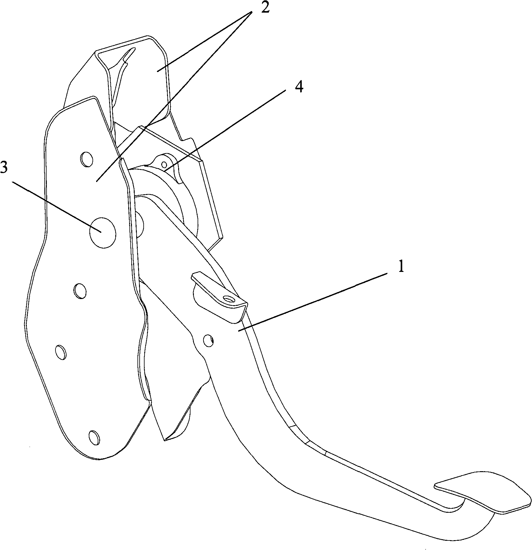
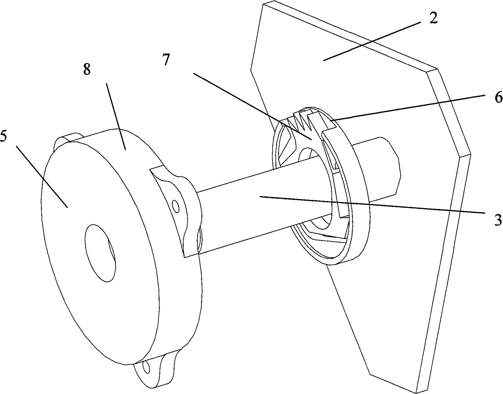
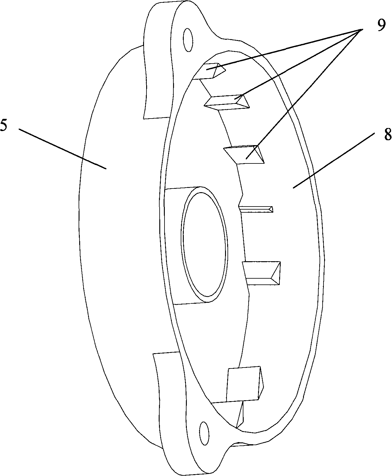
[0014] Such as figure 1 , figure 2 and image 3 As shown, the brake pedal provided by the present invention includes a pedal arm 1 and a bracket 2, the pedal arm 1 is pivotally connected to the bracket 2 through a rotating shaft 3, wherein the brake pedal also includes a safety device 4, and the safety device 4 Located between the bracket 2 and the pedal arm 1 and the rotating shaft 3 runs through the safety device 4, the safety device 4 includes a housing 5 and a ratchet disc 6, the housing 5 is fixedly connected to the bracket 2, and the housing 5 has A flange 8 axially extending along the rotating shaft 3, the inner surface of the flange 8 is provided with teeth 9, the ratchet disk 6 is located in the housing 5 and fixedly connected with the rotating shaft 3, the ratchet A ratchet 7 is provided on the disc 6, and the ratchet 7 is elast...


PUM


Abstract

The invention provides a brake pedal which comprises a pedal arm and a bracket; the pedal arm is connected with a pivot of the bracket by a rotating shaft, wherein, the brake pedal also comprises a safety device which is positioned between the bracket and the pedal arm and penetrated by the rotating shaft; the safety device comprises a shell body and a pawl plate; the shell body is fixedly connected with the bracket and provided with a flange axially extending along the rotating shaft; the surface of the inner side of the flange is provided with teeth; the pawl plate is positioned in the shell body and is fixedly connected with the rotating shaft; pawls which can be meshed with the teeth are arranged on the pawl plate; the pawls are elastically connected with the pawl plate, wherein, the safety device also comprises an actuating device used for causing the pawls to extend or not to extend out of the flange of the pawl plate. When comparatively great impact is caused by the crash of a vehicle, the brake pedal provided by the invention can restrict the rotation of the rotating shaft, thereby preventing the pedal arm from moving towards a driver suddenly.

Description

technical field [0001] The present invention relates to a brake pedal for a vehicle, and more particularly to a safety brake pedal which can lock the pedal arm when the vehicle is subjected to a large impact such as a collision, thereby preventing the pedal from cause injury to the driver. Background technique [0002] When the vehicle is subjected to a severe impact, such as a collision, the position changes of the brake master cylinder and the booster will cause the ordinary brake pedal to rotate in the opposite direction. Or the leg collides, thereby causing injury to the driver. [0003] In order to solve this problem, CN1310788C discloses a brake pedal installation structure, the brake pedal installation structure includes: a hinge pipe; and a pedal arm formed with a hinge groove, wherein the hinge groove is connected to the hinge pipe, A part of the hinge pipe is opened to the front of the vehicle, and its width is smaller than the width of the outer diameter of the ...

Claims


Application Information

Patent Timeline
Patent Type & Authority Applications(China)
IPC IPC(8): B60R21/09
Inventor 凌胜宋佑川袁野胡庚伟
Owner BYD CO LTD
Why Eureka
Try Eureka