Electric dust collector

A vacuum cleaner and electric technology, which is applied in the direction of vacuum cleaners, electrical components, electromechanical devices, etc., can solve the problems of inability to realize commutator motor protection in the early stage, high price of thermal fuses, and high cost of electric vacuum cleaners

Inactive Publication Date: 2009-02-04
SHARP KK
View PDF2 Cites 5 Cited by
  • Summary
  • Abstract
  • Description
  • Claims
  • Application Information

AI Technical Summary

Problems solved by technology

[0004] However, as disclosed in JP-A-8-168212 and JP-A-2002-199661, in the configuration of using a thermal fuse to protect the commutator motor from abnormal sparks, the temperature of the commutator motor will not reach the temperature of the thermal fuse. The generation of abnormal sparks in commutator motors cannot be detected before the set temperature
Therefore, for example, when abnormal sparks are generated intermittently or the temperature of the commutator motor rises slowly, detection of the occurrence of abnormal sparks may be delayed, and there is a problem that the protection of the commutator motor cannot be realized early.
In addition, since thermal fuses are generally expensive, there is also a problem that the cost of electric vacuum cleaners increases in the configuration using such thermal fuses.

Method used


Image

  • Electric dust collector
  • Electric dust collector
  • Electric dust collector

Examples


Embodiment Construction

[0020] Embodiments of the present invention will be described below with reference to the drawings for understanding of the present invention. In addition, the following embodiment is an example which actualized this invention, and is not a characteristic which limits the technical scope of this invention.

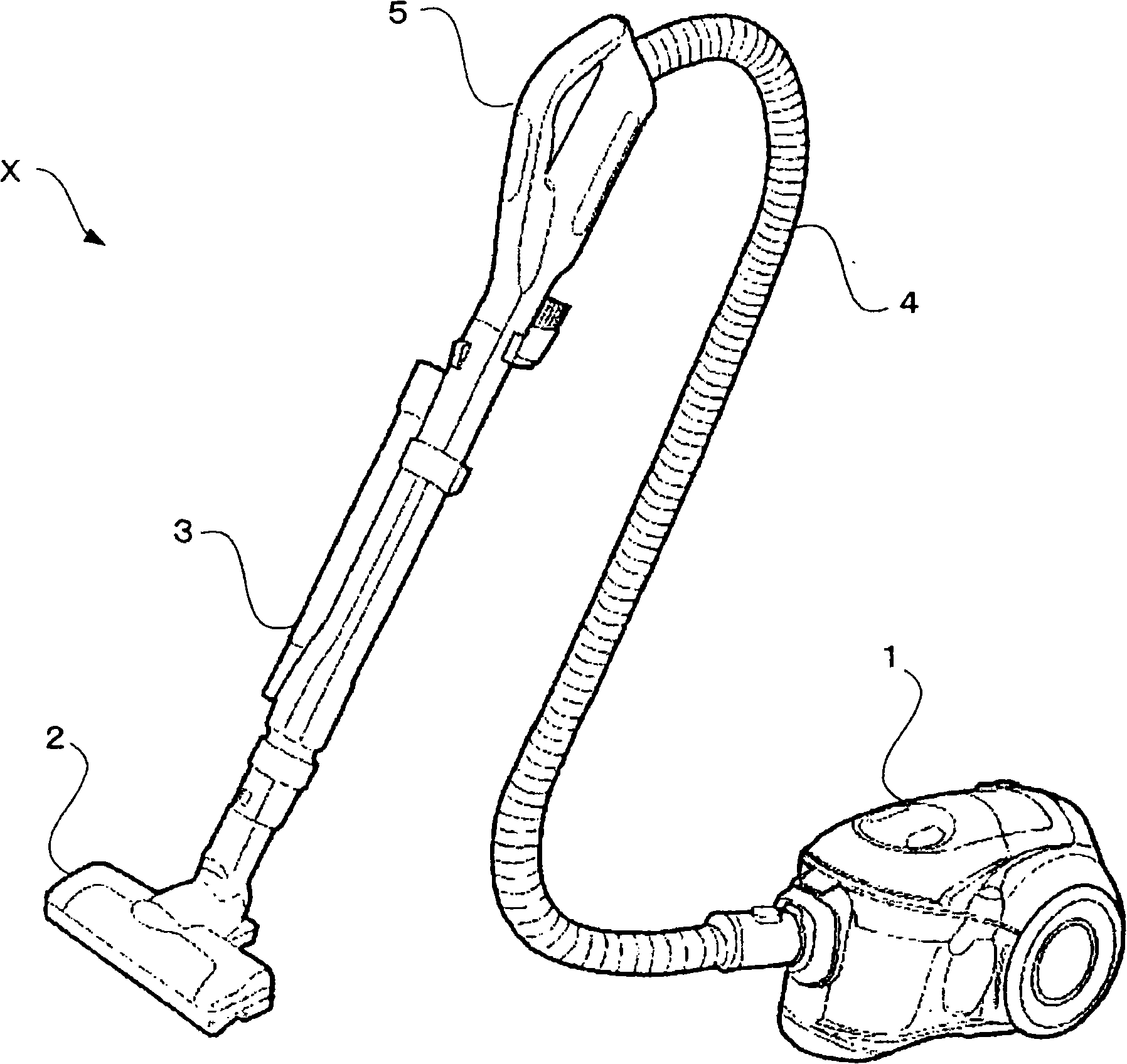
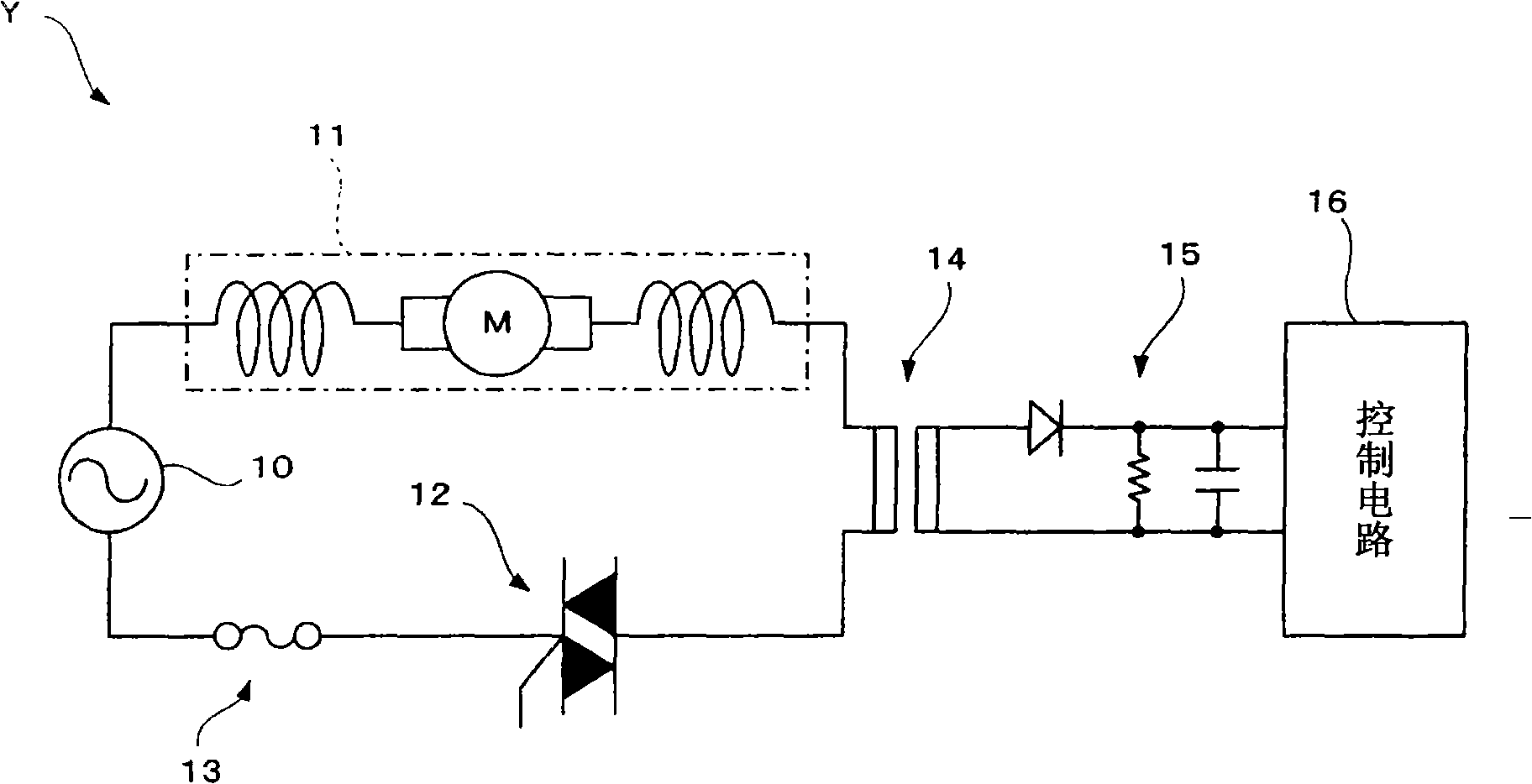
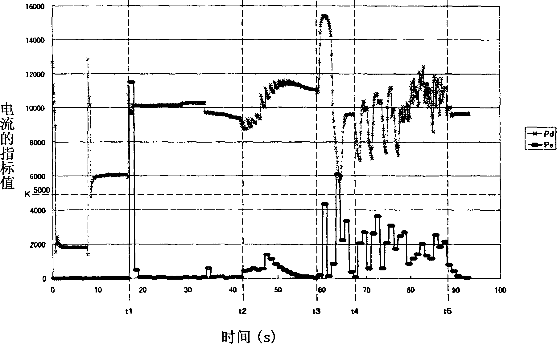
[0021] here, figure 1 It is an external view of an electric vacuum cleaner X according to an embodiment of the present invention, figure 2 It is a circuit diagram of a motor drive circuit Y to which a commutator motor 11 provided in an electric vacuum cleaner X according to an embodiment of the present invention is connected, image 3 and Figure 4 It is a figure which shows an example of the measurement result of the electric current value Pd of the commutator motor 11 in electric vacuum cleaner X concerning embodiment of this invention, and its change range Pe, Figure 5 It is a flowchart showing an example of the procedure of the abnormal spark prevention process ex...


PUM


Abstract

The invention provides an electric vacuum cleaner for detecting the changing extent (S1-S3) for the current in the circuit in the rectification motor according to the stated time; the detected changing extent of the current reaches the upper limit established in the fixed number of times that is established in advance in advance in order to the unusual spark takes place in the motor of the stated commentator to measure above threshold value is established The unusual number of times as a condition (the YES side of S4), which makes the rectification motor stop (S5); thereby, the invention achieves the protection of the rectification motor when generating the abnormal spark as early as possible.

Description

technical field [0001] The present invention relates to an electric vacuum cleaner using a commutator motor (motor) having a stator (brush) and a commutator (rotor), and particularly relates to a technique for realizing protection of the commutator motor when abnormal sparks are generated in the commutator motor . Background technique [0002] Conventionally, a commutator motor having a stator (brush) and a commutator (rotor) is used for an electric blower used to suck dust with an electric vacuum cleaner (for example, refer to Patent Documents 1 and 2). In this commutator motor, sparks (hereinafter, referred to as "abnormal sparks") are sometimes generated when the commutator rotates in sliding contact with the energized stator. In addition, if abnormal sparks are generated in the commutator motor, the temperature inside the commutator motor may rise abnormally, which may cause burnout of the commutator motor or wear of components such as a stator. [0003] On the other h...

Claims


Application Information

Patent Timeline
Patent Type & Authority Applications(China)
IPC IPC(8): H02K13/00H02H7/08A47L9/00
Inventor 立山裕
Owner SHARP KK
Why Eureka
Try Eureka