Lead sealing structure of ammeter

A technology of lead sealing and electric meter, which is applied to seals, stamps, instruments, etc., can solve the problems of low production efficiency, high cost, and low efficiency of lead sealing, and achieve the effects of high production efficiency, improved efficiency, and simple structure

Inactive Publication Date: 2010-09-15
武建华
View PDF5 Cites 0 Cited by
  • Summary
  • Abstract
  • Description
  • Claims
  • Application Information

AI Technical Summary

Problems solved by technology

[0002] In order to prevent the ammeter from being opened at will, the existing ammeters all adopt such figure 1 In the lead seal structure shown, screw holes (not shown in the figure) and lugs 40 with wire holes are provided on the upper cover 1 of the electric meter, and threaded columns (not shown in the figure) are provided in the base 2 of the electric meter. out), connect the seal screw 10 with the threading hole through the screw hole of the upper cover 1 and the threaded column of the base 2 so that the upper cover 1 and the base 2 are connected and fixed, and then pass the seal wire 30 respectively through the lugs 40 and the threading hole of the lead seal screw 10, and finally the two ends of the lead seal line 30 are closed and fixed by the lead seal block 20. This lead seal screw 10 has a threading hole, so that its cost is relatively high, and at the same time The process of lead sealing is relatively complicated, and the efficiency of lead sealing is low. Therefore, the lead sealing structure of this traditional electric meter has the following disadvantages: complex structure, high cost, and low production efficiency

Method used


Image

  • Lead sealing structure of ammeter
  • Lead sealing structure of ammeter
  • Lead sealing structure of ammeter

Examples


Embodiment Construction

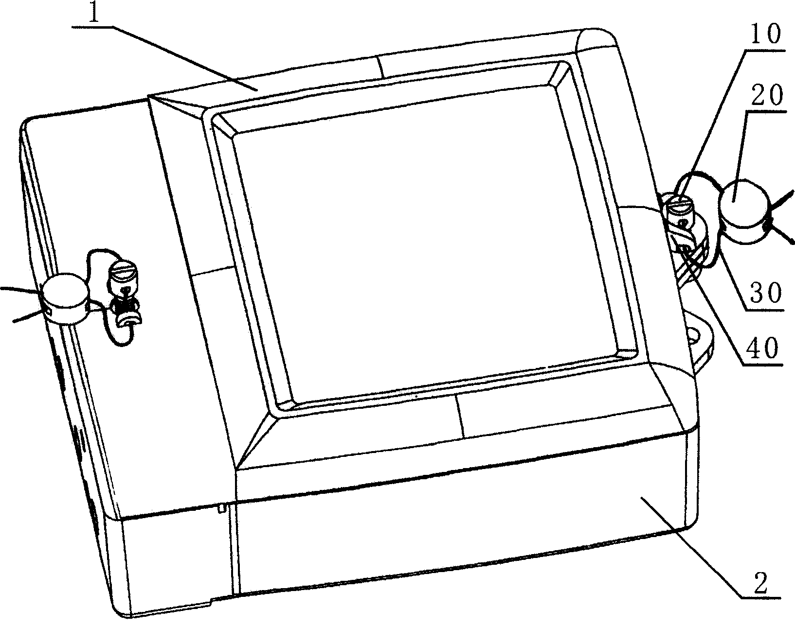
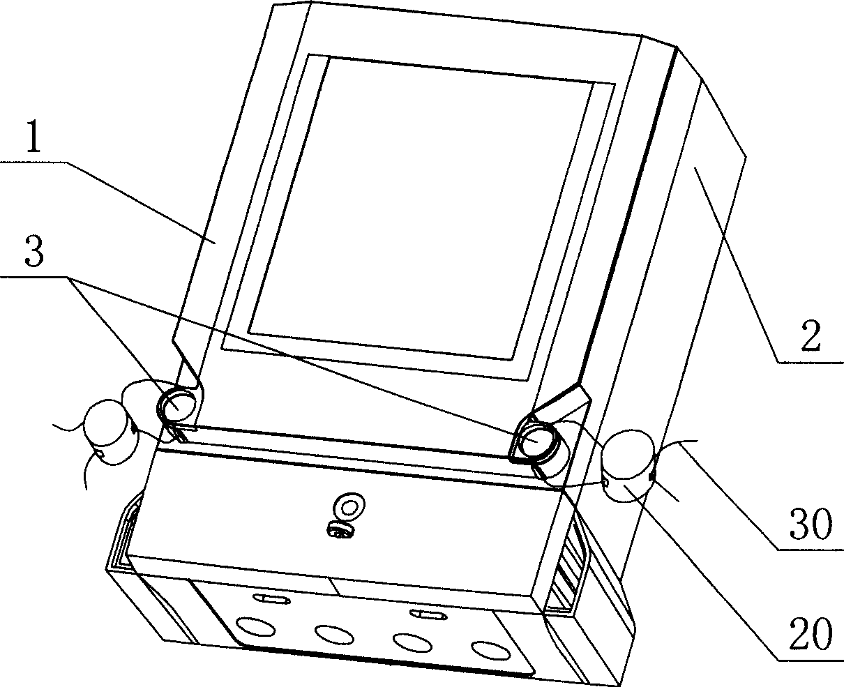
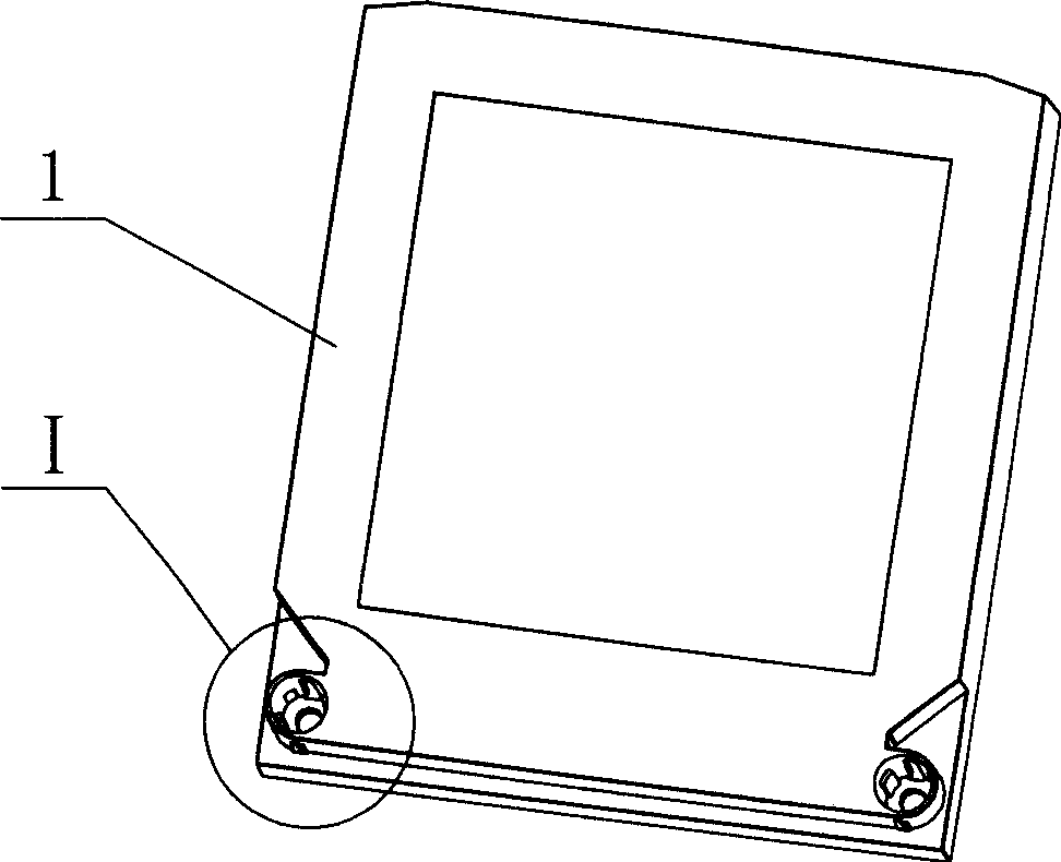
[0022] Such as Figure 2 to Figure 10 As shown, the electric meter of the present invention includes a loam cake 1 and a base 2, and the loam cake 1 is fixedly connected to the base 2, and the seal structure of the electric meter includes a lead seal block 20, a lead seal wire 30, screws, Lead seal cap 3, the upper cover 1 is provided with a cap body 11, the bottom of the cap body 11 is provided with screw holes 12, and the side of the cap body 11 is provided with two wire holes 13, so The tail of the screw (not shown in the figure) passes through the screw hole 12 and is connected with the base 2 so that the upper cover 1 is fixedly connected with the base 2, and the lead seal cap 3 includes a cap body 31, the side of the cap body 31 is provided with two threading holes 33, the cap body 31 is embedded in the cap body 11 and fixed, the two threading holes 33 are connected with the two threading holes 13 respectively Corresponding positions, the lead sealing wire 30 passes thr...


PUM


Abstract

The invention discloses an lead seal structure of electric meter with simple structure, low cost and high production efficiency. The electric meter includes an upper cover 1 and a base 2, the lead seal structure of electric meter includes an lead seal block 20, an lead seal line 30, a screw and an lead seal cap 3, a cap containing body 11 is arranged on the upper cover 1, a screw hole 12 is arranged on the bottom of the cap containing body 11, two overline holes 13 are arranged on the side of the cap containing body 11, the end of the screw passes through the screw hole 12 and is connected with the base 2, the lead seal cap 3 includes a cap body 31, the two threading holes 33 are arranged on the side of the cap body 31 which is fixed in the cap containing body 11, the two threading holes 33 are corresponding to the two overline holes 13 respectively, the lead seal line 30 passes through the threading holes 33 and the overline holes 13 in order, and the two ends of the lead seal line 30 are closely fixed through the lead seal block 20. The invention can be extensively used for electric meter field.

Description

technical field [0001] The invention relates to a lead seal structure of an electric meter. Background technique [0002] In order to prevent the ammeter from being opened at will, the existing ammeters all adopt such figure 1 In the lead seal structure shown, screw holes (not shown in the figure) and lugs 40 with wire holes are provided on the upper cover 1 of the electric meter, and threaded columns (not shown in the figure) are provided in the base 2 of the electric meter. out), connect the seal screw 10 with the threading hole through the screw hole of the upper cover 1 and the threaded column of the base 2 so that the upper cover 1 and the base 2 are connected and fixed, and then pass the seal wire 30 respectively through the lugs 40 and the threading hole of the lead seal screw 10, and finally the two ends of the lead seal wire 30 are sealed and fixed by the lead seal block 20. This lead seal screw 10 has a threading hole, so its cost is relatively high, and at the sa...

Claims


Application Information

Patent Timeline
Patent Type & Authority Patents(China)
IPC IPC(8): G09F3/03
Inventor 武建华
Owner 武建华
Why Eureka
Try Eureka