Zoom lens system and image pickup device containing above system

一种变焦透镜、负透镜的技术,应用在电视系统的零部件、图像通信、彩色电视的零部件等方向,能够解决紧凑性高光学性能困难等问题,达到满意光学性能、实现光学性能的效果

Active Publication Date: 2009-03-11
CANON KK
View PDF0 Cites 2 Cited by
  • Summary
  • Abstract
  • Description
  • Claims
  • Application Information

AI Technical Summary

Problems solved by technology

[0016] If the construction of the first lens unit is not appropriate, it is very difficult to achieve high optical performance throughout the zoom range while maintaining compactness and high zoom ratio

Method used


Image

  • Zoom lens system and image pickup device containing above system
  • Zoom lens system and image pickup device containing above system
  • Zoom lens system and image pickup device containing above system

Examples


example 1-5

[0166] Numerical examples 1 to 5 corresponding to the first to fifth exemplary embodiments will be given below.

[0167] In each numerical example, i represents the order of lens surfaces counted from the object side, Ri represents the radius of curvature of the lens surface, Di represents the lens thickness and air gap between the i-th surface and the (i+1)-th surface, and Ni Represents the refractive index of the d-line, vi represents the Abbe number, and θgf represents the partial dispersion ratio.

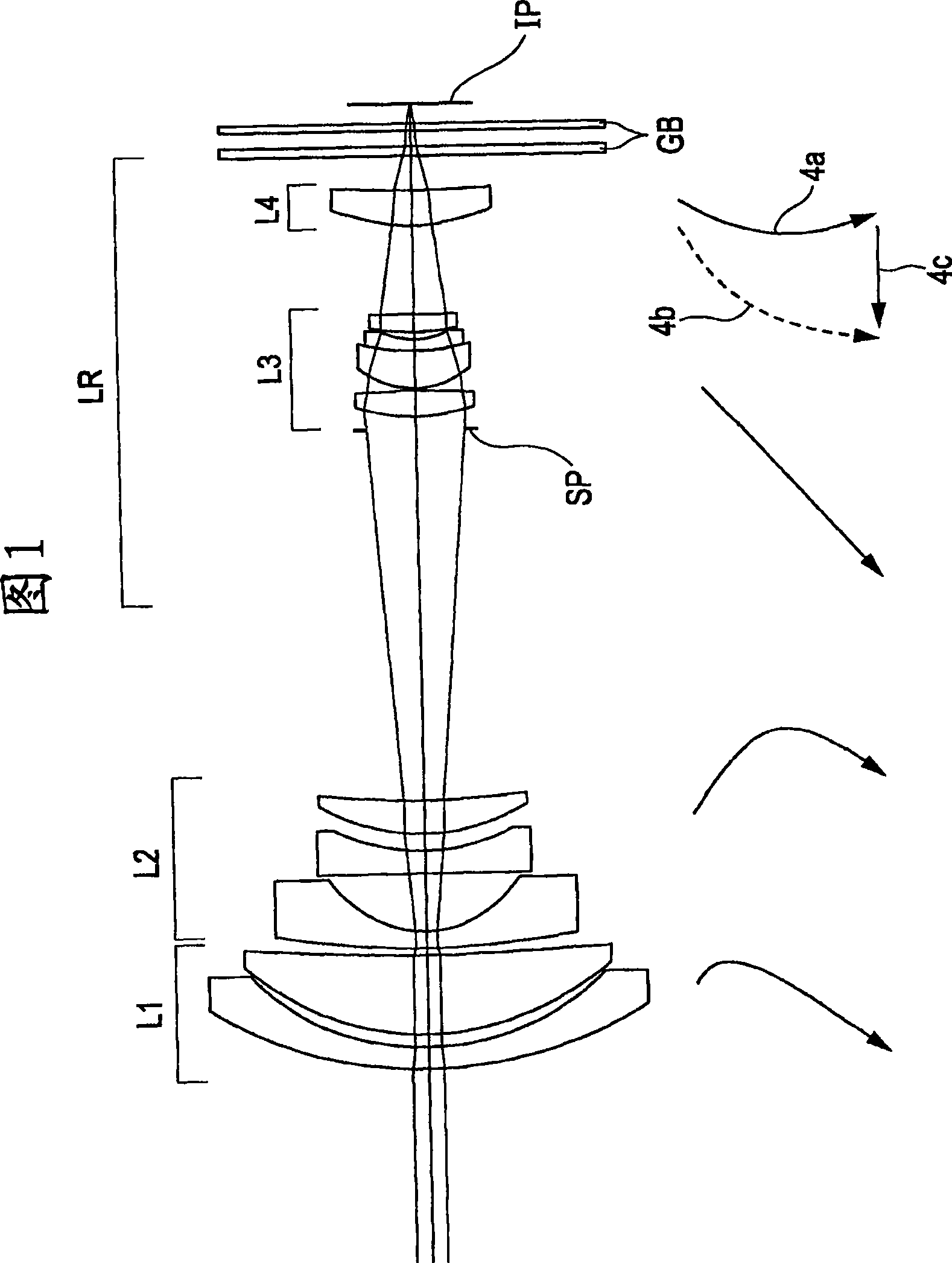
[0168] The four surfaces closest to the image side correspond to, for example, an optical block GB or a color synthesis prism.

[0169] Denote the focal length, f-number, and half angle of view as f, FNO, and ω, respectively.

[0170] Denote the aspheric coefficients as k, A, B, C, D and E.

[0171] When the displacement of the surface vertex at the height h from the optical axis in the direction of the optical axis is expressed as x, the shape of the aspheric surface is expr...

example 1

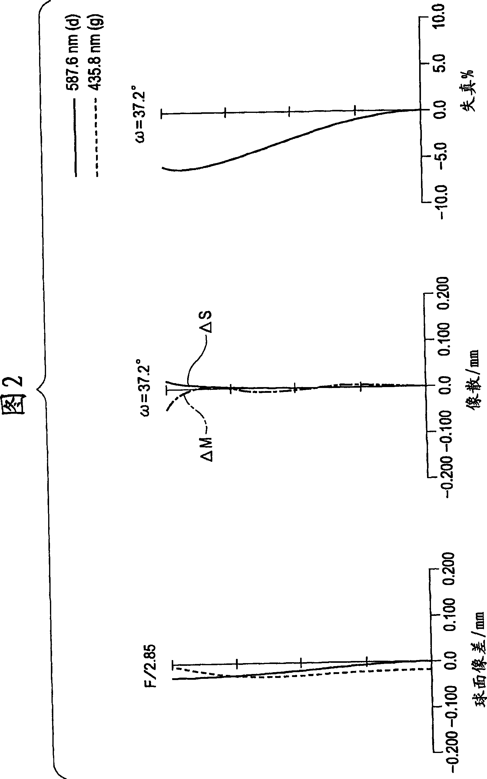
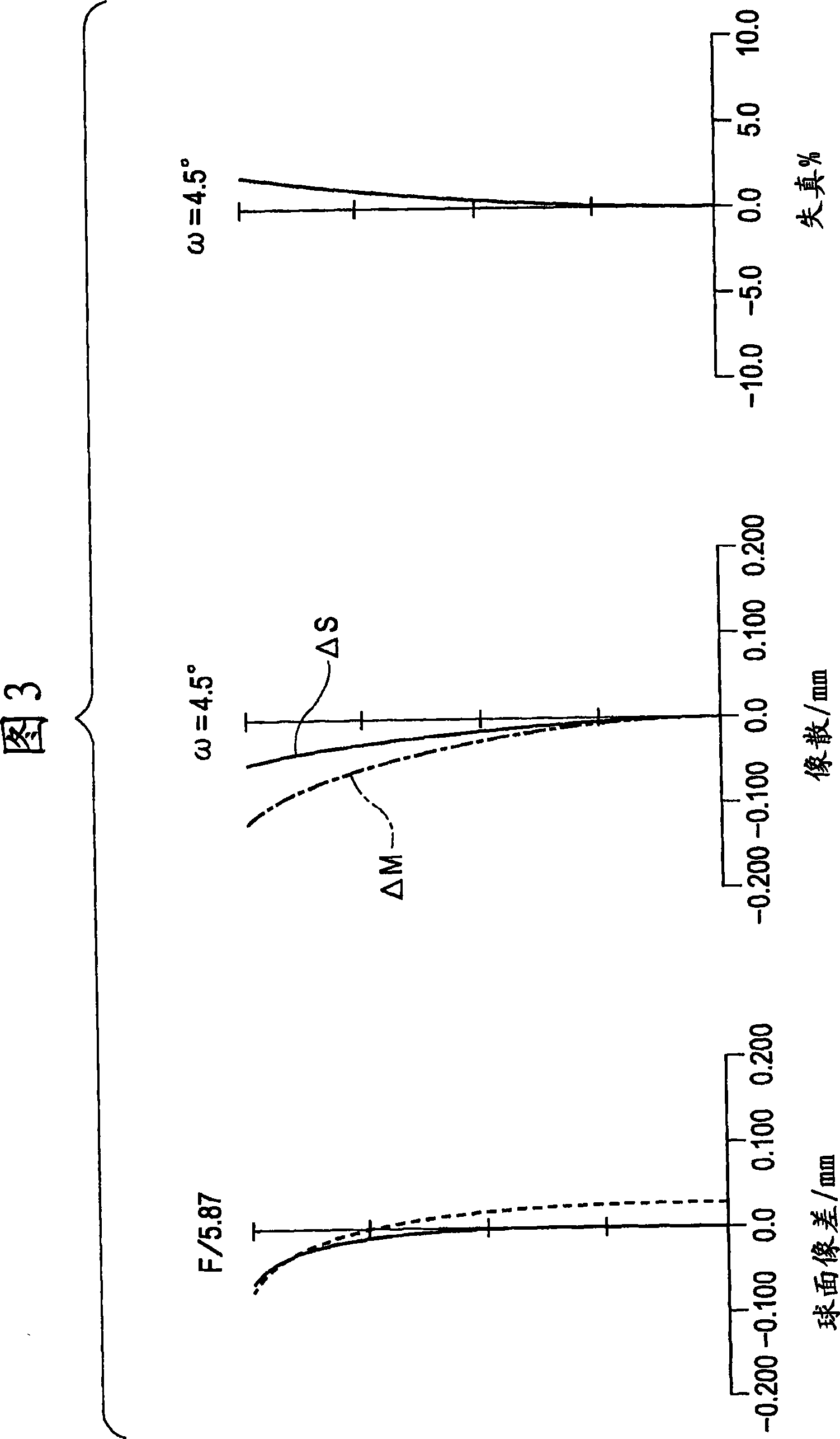
[0176] f: 4.8~46.0mm FNO: 2.85~5.87 ω: 37.21~4.52°

[0177] R D N v θgF

[0178] 1 24.037 1.20 1.847 23.8

[0179] 2 14.388 0.80 1.633 23.0 0.6747

[0180] 3 15.748 4.60 1.772 49.6

[0181] 4 151.929 (variable)

[0182] 5 52.003 0.95 1.883 40.8

[0183] 6 6.627 3.28

[0184] 7 (Aspherical) 1.35 1.860 40.3

[0185] 8 12.158 0.99

[0186] 9 12.279 1.91 1.923 18.9

[0187] 10 49.360 (variable)

[0188] 11 (aspherical) 1.50 1.678 55.3

[0189] 12 -80.221 0.10

[0190] 13 4.838 2.19 1.487 70.2

[0191] 14 12.070 0.60 2.003 28.3

[0192] 15 4.221 0.40

[0193] 16 16.466 1.18 1.487 70.2

[0194] 17 -34.172 (variable)

[0195] 18 (aspherical) 2.00 1.487 70.2

[0196] 19 36.606 (variable)

[0197] 20 inf. 0.60 1.516 64.1

[0198] 21 inf. 0.90

[0199] 22 inf. 0.40 1.516 64.1

[0200] 23 inf.

[0201] interval data

[0202] W T

[0203] d4 0.40 17.57

[0204] d10 21.91 2.41

[0205] d17 4.96 22.39

[0206] d19 1.98 1.26

[0207] Aspheric ...

example 2

[0215] f: 4.7~31.6mm FNO: 2.88~5.67 ω: 37.17~6.44°

[0216] R D N v θgF

[0217] 1 (aspherical) 0.50 1.633 23.0 0.6747

[0218] 2 26.434 4.67 1.678 55.3

[0219] 3 -79.835 1.00 1.847 23.8

[0220] 4 332.271 (variable)

[0221] 5 44.219 1.00 1.772 49.6

[0222] 6 6.788 2.87

[0223] 7 (Aspherical) 1.40 1.860 40.3

[0224] 8 9.980 1.38

[0225] 9 11.273 1.81 1.923 18.9

[0226] 10 30.555 (variable)

[0227] 11 (aspherical) 1.50 1.589 61.1

[0228] 12 -24.353 0.10

[0229] 13 4.734 1.90 1.589 61.1

[0230] 14 13.243 0.60 2.003 28.3

[0231] 15 4.119 0.71

[0232] 16 -65.346 1.15 1.487 70.2

[0233] 17 -13.219 (variable)

[0234] 18 11.706 2.36 1.516 64.1

[0235] 19 -718.292 (variable)

[0236] 20 inf. 0.60 1.516 64.1

[0237] 21 inf. 0.90

[0238] 22 inf. 0.40 1.516 64.1

[0239] 23 inf.

[0240] interval data

[0241] W T

[0242] d4 0.48 12.66

[0243] d10 19.50 2.41

[0244] d17 4.44 24.55

[0245] d19 1.90 3.23

[0246] Aspheric Shap...


PUM


Abstract

A zoom lens system includes, in order from an object side to an image side, a first lens unit having a positive refractive power, a second lens unit having a negative refractive power, and a subsequent lens-unit set including at least one lens units. Intervals between the lens units change during zooming. The first lens unit includes a negative lens element, an optical element, and a positive lens element. Various parameters are set appropriately, including the Abbe number nun and the partial dispersion ratio thetagF of a material composing the optical element, the focal length f1n of the negative lens element and the Abbe number nu1n of a material composing the negative lens element, the focal length f1 of the first lens unit, and respective lateral magnifications beta3iw and beta3it of the subsequent lens-unit set at a wide-angle end and at a telephoto end.

Description

technical field [0001] The present invention relates to a zoom lens system and an image pickup apparatus including the zoom lens system, and particularly to a zoom lens system included in image pickup apparatuses such as digital still cameras, video cameras, film cameras, and broadcast cameras. Background technique [0002] As the pixel density of solid-state image pickup devices increases, the latest image pickup apparatuses (cameras) provided with solid-state image pickup devices, such as video cameras and digital still cameras, are highly functional and small in size. It is desirable that a zoom lens system serving as an image pickup optical system to be included in such an image pickup apparatus be compact and have a high zoom ratio. [0003] Examples of a zoom lens system having a high zoom ratio include a positive-lead zoom lens system in which the first lenses having positive refractive power are arranged in order from the object side to the image side. A lens unit, ...

Claims


Application Information

Patent Timeline
Patent Type & Authority Applications(China)
IPC IPC(8): G02B15/16G02B9/34G02B9/60H04N5/225
CPCG02B15/173G02B15/143105
Inventor 和田健
Owner CANON KK
Why Eureka
Try Eureka