Imaging lens and optical apparatus

a technology of optical apparatus and lens, applied in the field of imaging lens and optical apparatus, can solve the problems of different field curvature of a design value, increased length of entire lens system, and increased size of the entire lens system, so as to achieve satisfactory optical performance and reduce size

Active Publication Date: 2018-03-29
FUJIFILM CORP
View PDF1 Cites 2 Cited by
  • Summary
  • Abstract
  • Description
  • Claims
  • Application Information

AI Technical Summary

Benefits of technology

[0033]According to the present invention, a lens system including, in order from an object side, a first lens group fixed during focusing and a positive second lens group moving to the object side during focusing from a long-distance object to a short-distance object is configured such that an adjustment group for adjusting a field curvature is disposed on a side closest to the object in the whole system, a stop which is fixed during the adjustment of the field curvature is disposed closer to an image side than this adjustment group, and predetermined conditional expressions are satisfied. Therefore, it is possible to provide an imaging lens, having satisfactory optical performance, which is capable of adjusting a field curvature while suppressing defocusing of the central portion of an imaging region and achieving a reduction in size, and an optical apparatus including this imaging lens.

Problems solved by technology

In a case where the lens system of a rear focus type or an inner focus type is attached to a camera having a significant error in a flange back, there is a problem in that a field curvature different from a design value occurs.
In addition, in a case where an imaging device that captures an image formed by an imaging lens has a curvature, there is a problem in that defocus occurs in the peripheral portion of the imaging device.
Further, in an FA field and a machine vision (MV) field, there is a desire for simultaneously observing subjects located at different distances, but there is a problem in that a general imaging lens of the related art is in focus only within one plane perpendicular to its optical axis.
Given such a situation, restrictions are put on a lens configuration, and thus there is a disadvantage that the entire lens system length increases.

Method used


Image

  • Imaging lens and optical apparatus
  • Imaging lens and optical apparatus
  • Imaging lens and optical apparatus

Examples


example 1

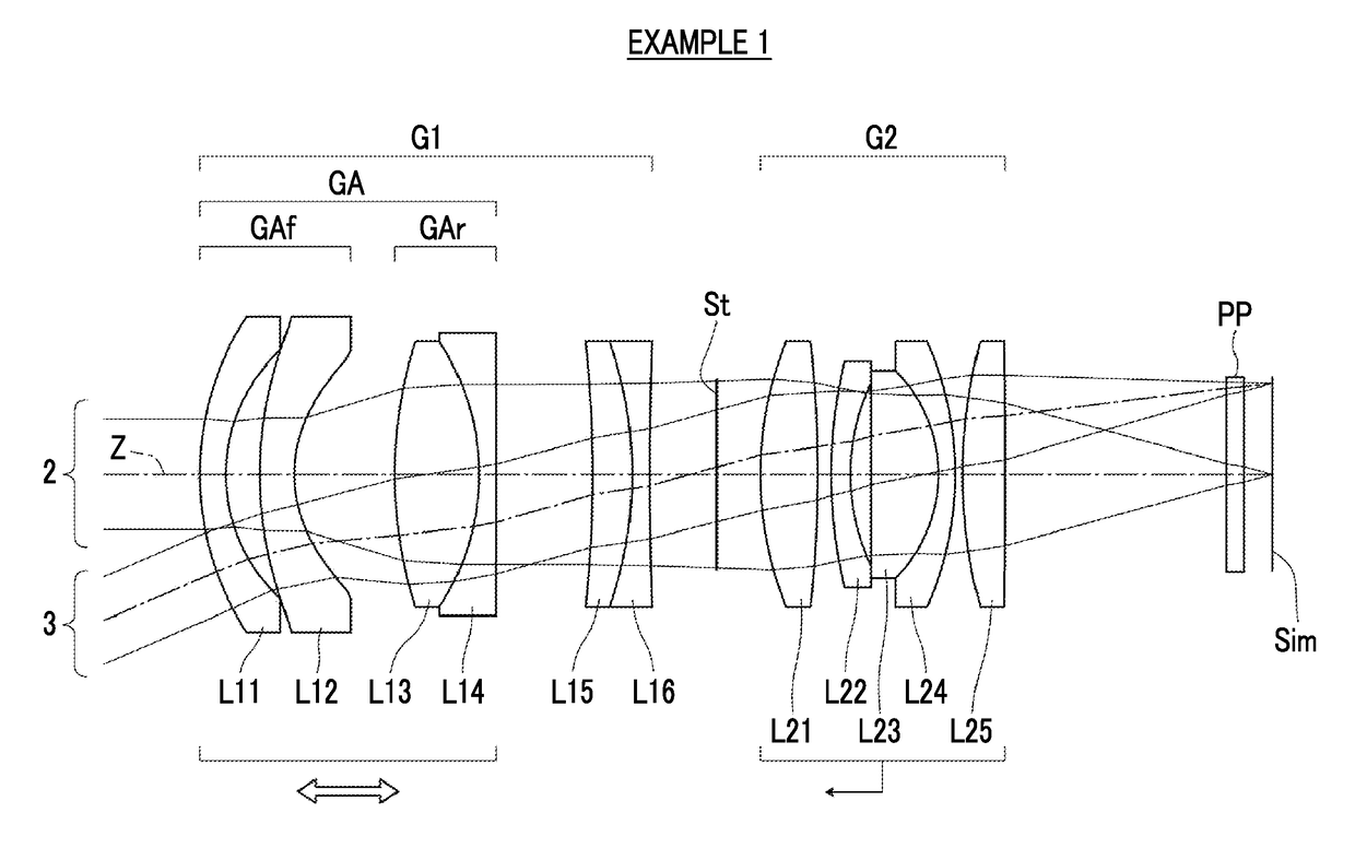
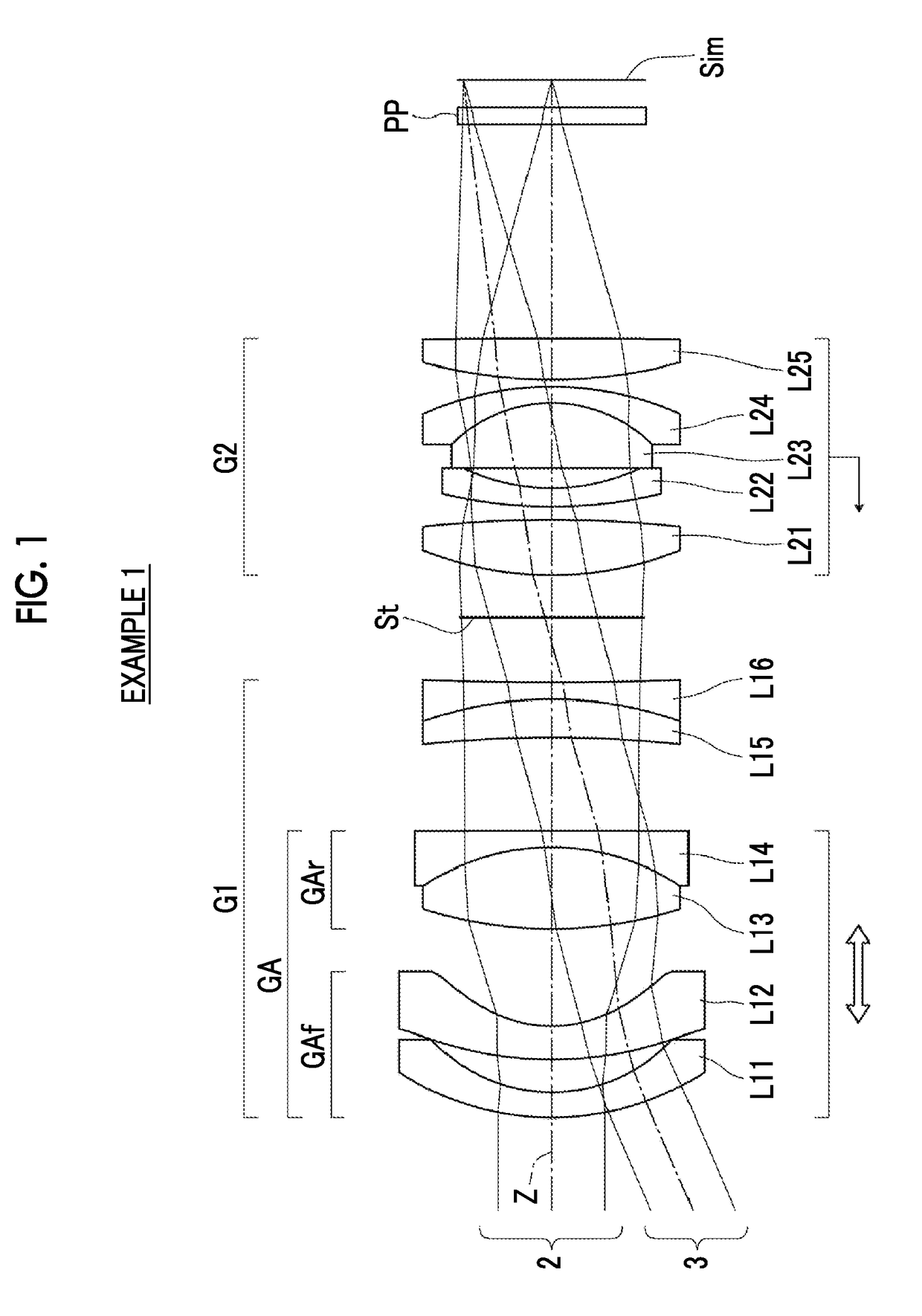
[0085]The lens configuration of an imaging lens of Example 1 is shown in FIG. 1, and the configuration thereof and a method of illustration thereof are as described. Therefore, the repeated description thereof will be partially omitted herein. The imaging lens of Example 1 consists of a first lens group G1, an aperture stop St, and a second lens group G2, in order from the object side. This imaging lens has a rear focus type adopted therein, and is configured such that, during focusing from an infinite object to a short-distance object, the first lens group G1 is fixed to an image plane Sim, and that the second lens group G2 and the aperture stop St integrally move from the image side to the object side.

[0086]The first lens group G1 consists of six lenses of lenses L11 to L16 in order from the object side. An adjustment group GA that adjusts a field curvature consists of some lenses of the first lens group G1. The adjustment group GA consists of a front group GAf and a rear group GA...

example 2

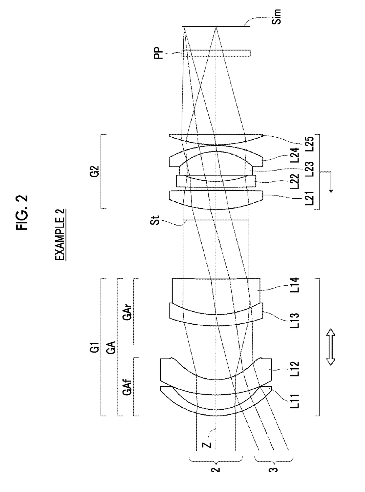
[0099]FIG. 2 shows a cross-sectional view of a lens configuration and an optical path of an imaging lens of Example 2. The imaging lens of Example 2 consists of a first lens group G1, an aperture stop St, and a second lens group G2, in order from the object side. This imaging lens has a rear focus type adopted therein, and is configured such that, during focusing from an infinite object to a short-distance object, the first lens group G1 is fixed to an image plane Sim, and that the second lens group G2 and the aperture stop St move integrally from the image side to the object side.

[0100]The first lens group G1 consists of four lenses of lenses L11 to L14 in order from the object side. An adjustment group GA that adjusts a field curvature is the entirety of the first lens group G1. The adjustment group GA consists of a front group GAf and a rear group GAr in order from the object side. The front group GAf consists of the lenses L11 and L12, and the rear group GAr consists of the lens...

example 3

[0102]FIG. 3 shows a cross-sectional view of a lens configuration and an optical path of an imaging lens of Example 3. The imaging lens of Example 3 consists of a first lens group G1, an aperture stop St, a second lens group G2, and a third lens group G3, in order from the object side. This imaging lens has an inner focus type adopted therein, and is configured such that, during focusing from an infinite object to a short-distance object, the first lens group G1 and the third lens group G3 are fixed to an image plane Sim, and that the second lens group G2 and the aperture stop St move integrally from the image side to the object side.

[0103]The first lens group G1 consists of five lenses of lenses L11 to L15 in order from the object side. An adjustment group GA that adjusts a field curvature is the entirety of the first lens group G1. The adjustment group GA consists of a front group GAf and a rear group GAr in order from the object side. The front group GAf consists of the lenses L1...


PUM


Abstract

The imaging lens includes a first lens group fixed during focusing and a positive second lens group moving to an object side during focusing from a long-distance object to a short-distance object, in order from a side closest to the object. The field curvature is adjusted by moving the first lens group or a sub-lens group within the first lens group including a lens closest to the object side, as an adjustment group. A stop fixed during the adjustment of the field curvature is disposed closer to an image side than the adjustment group. Conditional expressions relating to the focal length of the whole system, the focal length of the adjustment group, and the height of a paraxial on-axis light ray in the adjustment group are satisfied.

Description

BACKGROUND OF THE INVENTIONCROSS-REFERENCE TO RELATED APPLICATIONS[0001]The present application claims priority under 35 U.S.C. § 119 to Japanese Patent Application No. 2016-191322, filed on Sep. 29, 2016. The above application is hereby expressly incorporated by reference, in its entirety, into the present application.1. Field of the Invention[0002]The present invention relates to an imaging lens and an optical apparatus, and more specifically relates to an imaging lens, suitable for a factory automation (FA) camera, a digital camera, a surveillance camera, a cinema camera, a projection-type display device and the like, which is capable of adjusting a field curvature, and an optical apparatus including this imaging lens.2. Description of the Related Art[0003]In order to reduce aberration fluctuation due to the fluctuation of object distance in the aforementioned cameras, and to reduce aberration fluctuation due to the fluctuation of projection distance in the projection-type displa...

Claims


Application Information

Patent Timeline
Patent Type & Authority Applications(United States)
IPC IPC(8): G02B7/10G02B9/64G02B13/04
CPCG02B7/10G02B13/04G02B9/64G02B13/00G02B13/18
Inventor OKADA, KAZUYOSHIKUNUGISE, TAKASHIKISHINE, YASUNOBUCHO, MICHIO
Owner FUJIFILM CORP
Why Eureka
Try Eureka