Taking lens apparatus

a technology of lens apparatus and lens axis, which is applied in the direction of optics, instruments, diffraction gratings, etc., can solve the problems of difficult to meet all the requirements mentioned above simultaneously, difficult to maintain satisfactory optical performance, and inability to achieve satisfactory compactness along the optical axis, etc., to achieve satisfactory optical performance

Active Publication Date: 2009-03-24
MINOLTA CO LTD
View PDF11 Cites 3 Cited by
  • Summary
  • Abstract
  • Description
  • Claims
  • Application Information

AI Technical Summary

Benefits of technology

[0009]An object of the present invention is to provide a taking lens apparatus incorporating a compact, high-zoom-ratio zoom lens system that is composed of a small number of optical members but that nevertheless offers satisfactory optical performance over the entire zoom range.

Problems solved by technology

However, attempting to make a taking lens apparatus compact by reducing the weight and size of a taking lens system makes it difficult to maintain satisfactory optical performance.
However, with the zoom lens systems proposed in these publications, it is difficult to meet all the requirements mentioned above simultaneously.
For example, the zoom lens system proposed in Publication A has a four-unit zoom construction of a, from the object side thereof, positive-negative-positive-positive type, and includes a large number of lens elements, making it impossible to achieve satisfactory compactness along the optical axis.
The same is true with the zoom lens systems proposed in Publication B, which also include a rather large number of lens elements including a prism, making it impossible to achieve satisfactory compactness.

Method used


Image

  • Taking lens apparatus
  • Taking lens apparatus
  • Taking lens apparatus

Examples


examples

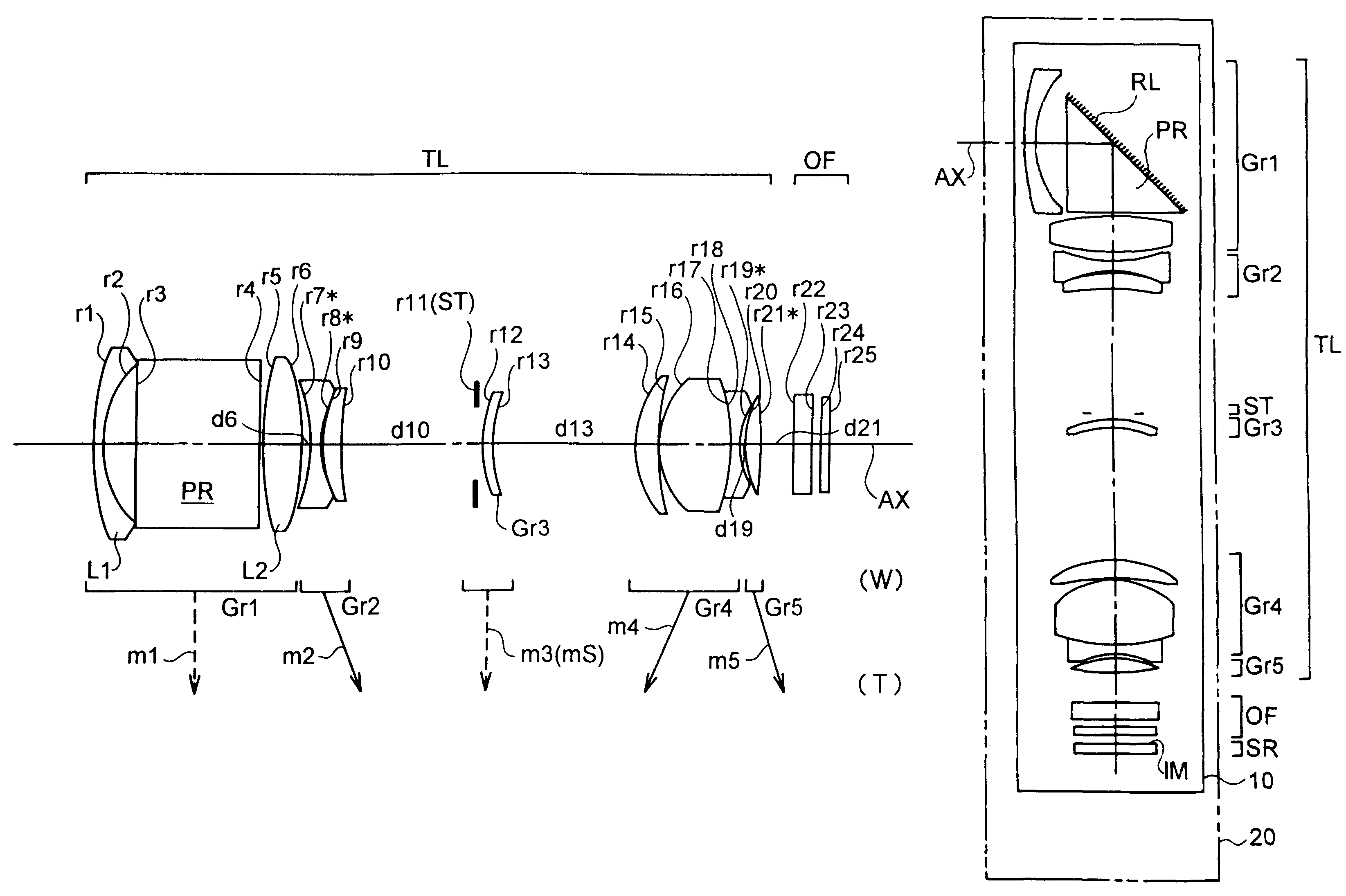
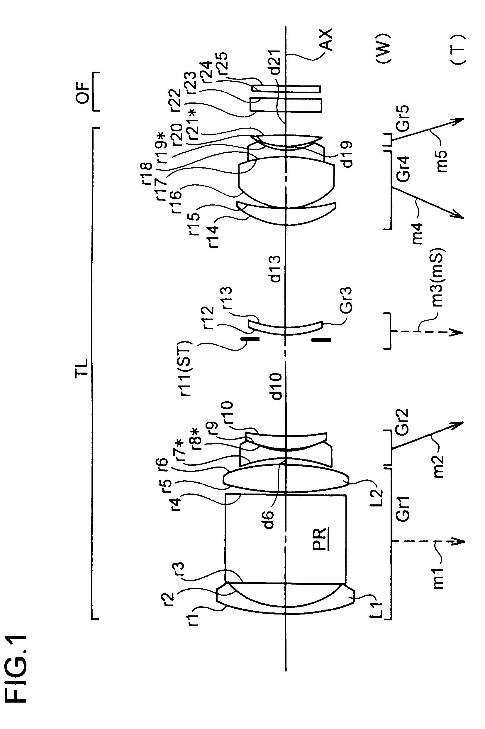
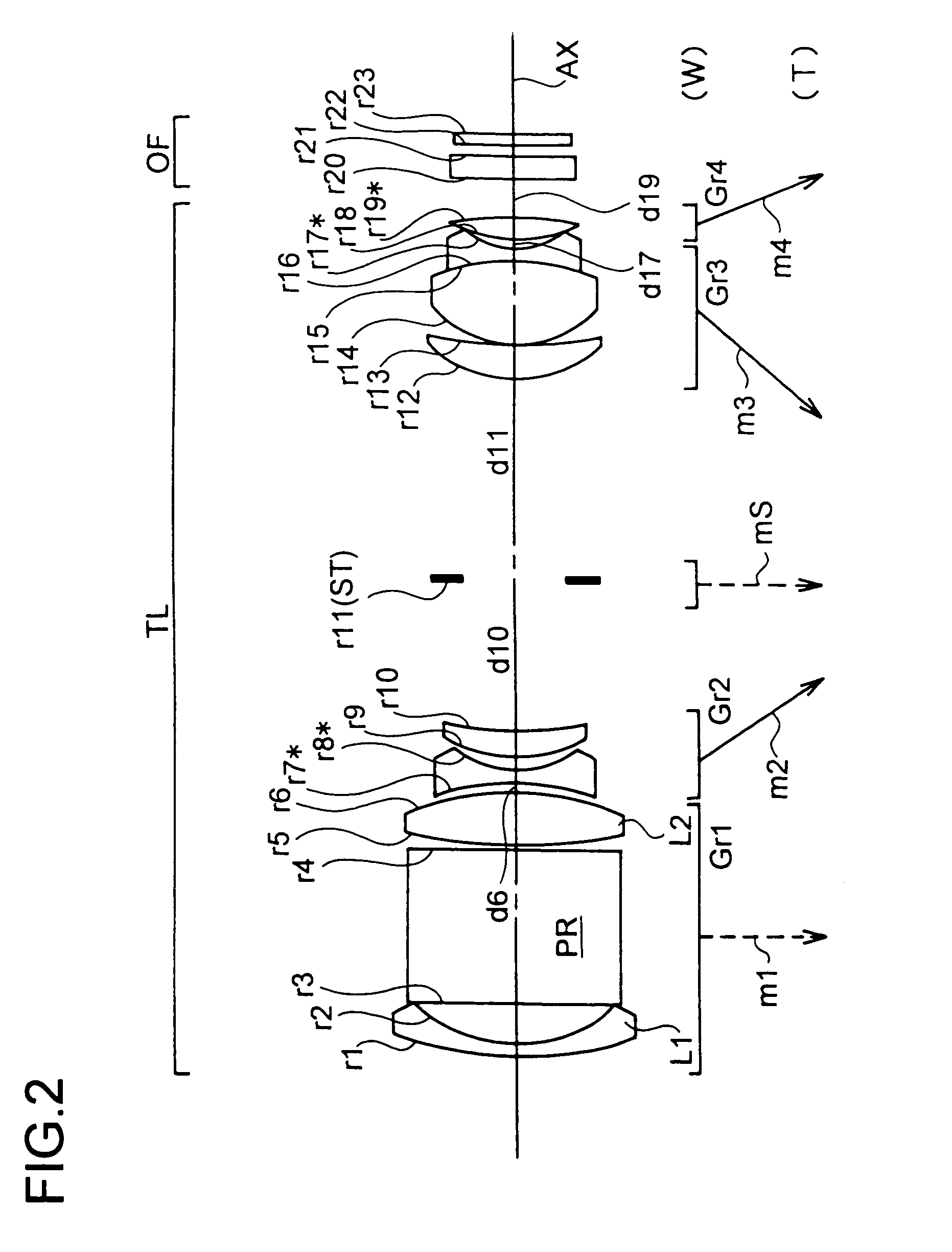
[0089]Hereinafter, practical examples of the construction and other features of the zoom lens system used in a taking lens apparatus embodying the present invention will be presented with reference to their construction data and other data. Examples 1 to 8 presented below are numerical examples corresponding to the first to eighth embodiments, respectively, described hereinbefore, and therefore the optical construction diagrams (FIGS. 1 to 8) of the first to eighth embodiments also show the lens construction of Examples 1 to 8, respectively.

[0090]Tables 1 to 8 show the construction data of Examples 1 to 8, respectively. In the construction data of each example, ri (i=1, 2, 3, . . . ) represents the radius of curvature (mm) of the i-th surface from the object side, di (i=1, 2, 3, . . . ) represents the i-th axial distance (mm) from the object side, and Ni (i=1, 2, 3, . . . ) and vi (i=1, 2, 3, . . . ) respectively represent the refractive index (Nd) for the d-line and the Abbe number...


PUM


Abstract

A taking lens apparatus has a zoom lens system that forms an optical image of an object at a variable magnification and that includes an aperture stop in the optical path, and an image sensor that has a light-receiving surface that converts the optical image into an electrical image signal and outputs it. The zoom lens system includes an optical member having a reflective surface that reflects a light beam in such a way that the optical axis is bent at substantially 90°. Moreover, prescribed conditions are fulfilled among the focal length of the entire zoom lens system at the wide-angle end, at the telephoto end, the axial distance from the image plane to the exit pupil at the wide-angle end, and the axial distance from the image-side surface of the most image-side lens element to the image plane.

Description

[0001]This application is based on Japanese Patent Application No. 2003-142381 filed on May 20, 2003, the contents of which are hereby incorporated by reference.BACKGROUND OF THE INVENTION[0002]1. Field of the Invention[0003]The present invention relates to a taking lens apparatus. More specifically, the present invention relates to a taking lens apparatus (a main component of a digital camera, video camera, or camera incorporated in or externally fitted to a personal computer, mobile computer, cellular phone, personal digital assistant (PDA), or the like) that optically takes in an image of a subject through a taking lens system and that then outputs it in the form of an electrical signal by means of an image sensor, and in particular to a taking lens apparatus incorporating a compact zoom lens system as its taking lens system.[0004]2. Description of the Prior Art[0005]In recent years, digital cameras, which use an image sensor such as a CCD (charge-coupled device) instead of silve...

Claims


Application Information

Patent Timeline
Patent Type & Authority Patents(United States)
IPC IPC(8): G02B15/14G02B15/20G02B5/04G02B13/00G02B13/18G02B15/173
CPCG02B15/173G02B5/04G02B15/144113G02B15/145129
Inventor KOJIMA, KAORI
Owner MINOLTA CO LTD
Why Eureka
Try Eureka