

Optical element holding device
A technology of optical components and fixing devices, applied in the directions of optical components, optics, electrical components, etc., can solve the problems of deformation of lens surface and mirror surface, deterioration of optical characteristics of lens and mirror, etc.
- Summary
- Abstract
- Description
- Claims
- Application Information
AI Technical Summary
Problems solved by technology
Method used
Image

Examples
no. 1 example
[0026] A first embodiment of the present invention will be described below with reference to FIGS. 1 to 5. FIG.
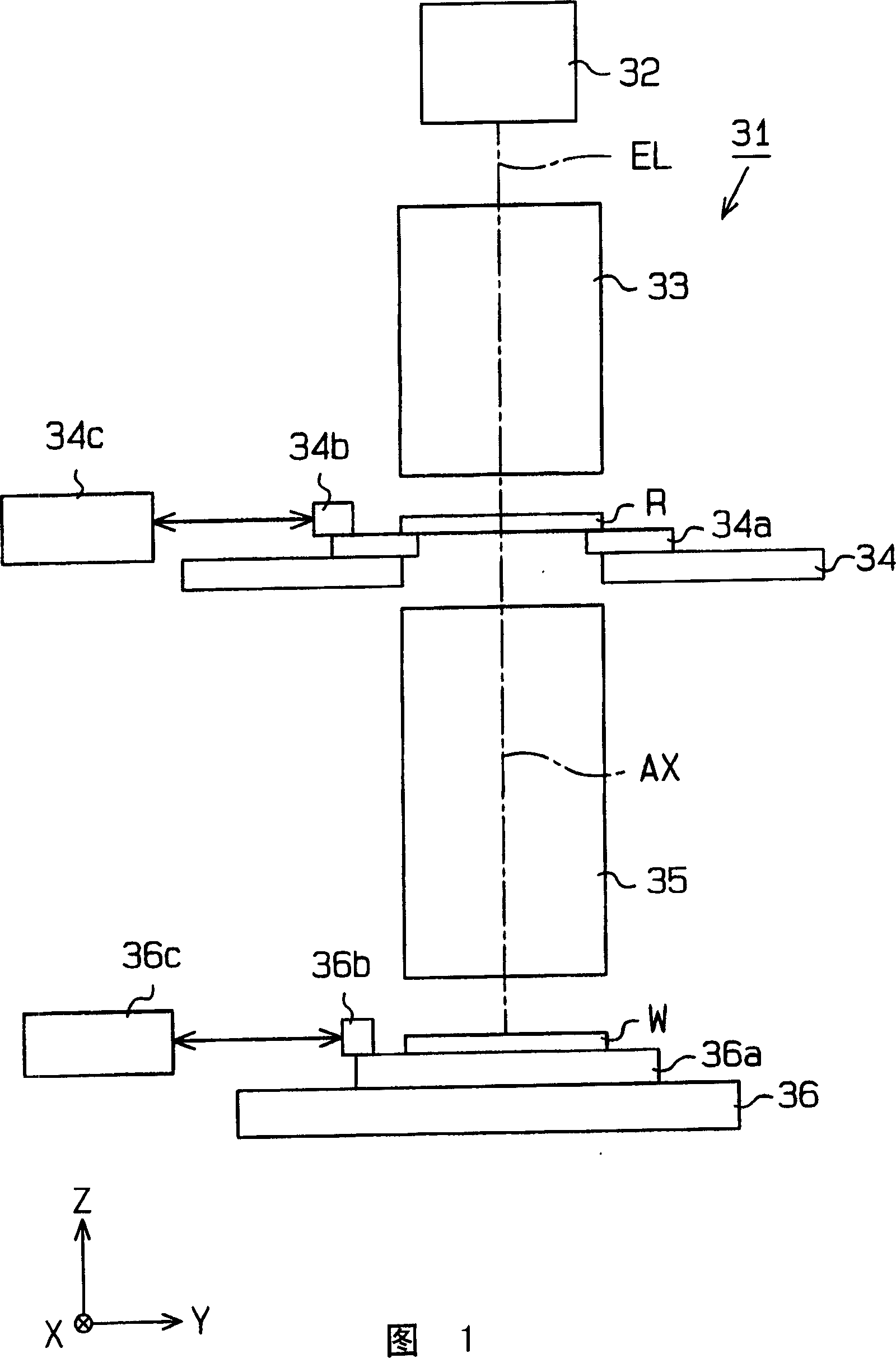
[0027] In this first embodiment, a scanning projection exposure apparatus of the so-called step-and-scan type includes a holding device implementing an optical element holding device according to the invention for holding an optical an element (for example, a lens, a mirror, or the like) such that its optical axis is oriented in the horizontal direction, or in an oblique direction inclined at a predetermined angle relative to the horizontal, the device Also included is a projection optics system partially embodying the tube according to the invention.
[0028] Fig. 1 schematically shows the configuration of the entire exposure apparatus including a catadioptric system as a projection optical system. In FIG. 1, the Z axis is set to be parallel to the reference optical axis AX of the catadioptric system, which includes the projection optical system 35; the Y axis is...
no. 2 example
[0062] The second embodiment of the present invention will be described below, mainly focusing on the differences from the first embodiment.
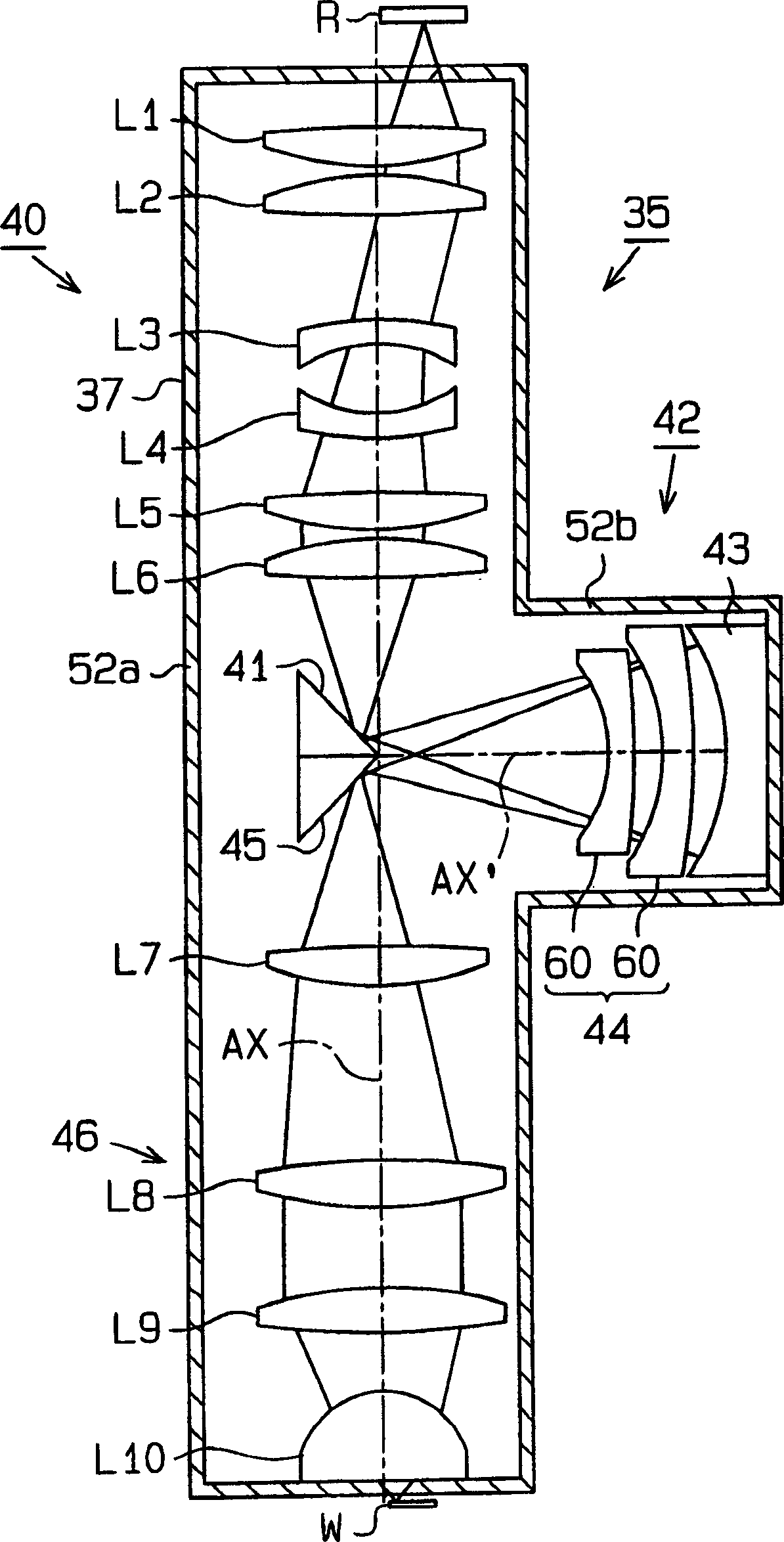
[0063] In the second embodiment, the configuration of the optical element fixing device 69 for fixing a concave mirror 43 vertically arranged in the second focusing optical system will be described in detail so that The orientation of the optical axis AX' is the horizontal direction.
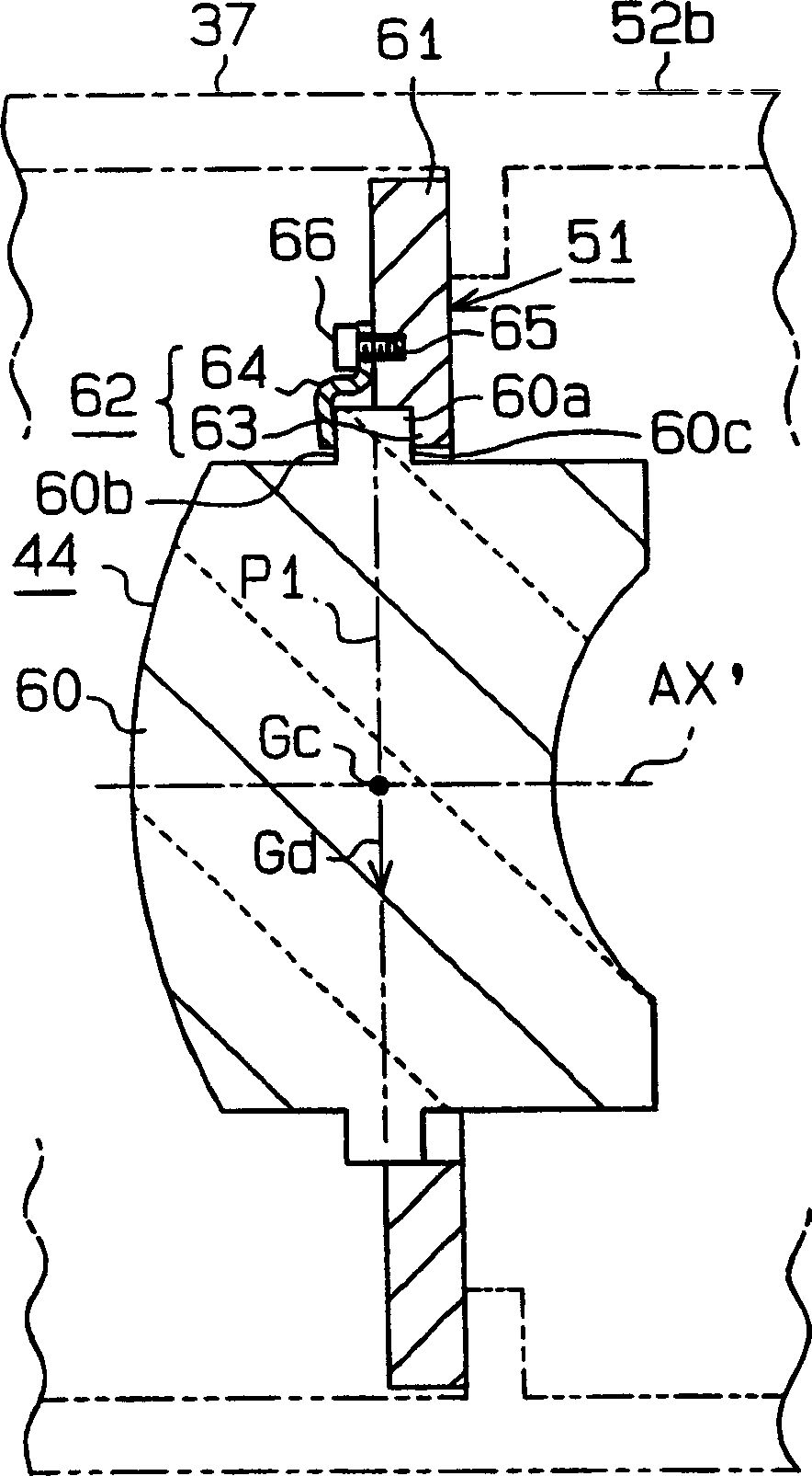
[0064] Figure 6 shows a sectional view of an optical element fixing device 69 according to a second embodiment, and Figure 7 An exploded perspective view of the optical element fixing device 69 according to the second embodiment is shown.
[0065] as in Figure 6 and 7 As shown in , the mirror 70, which is an optical element forming portion of the concave mirror 43, forms a flange 70a on the outer peripheral surface. The flange 70a includes a plane P1 that includes the center of gravity Gc of the mirror 70 when the mirror 70 is disposed in the vert...
no. 3 example
[0071] A third embodiment of the present invention will be described below, mainly focusing on differences from the second embodiment.
[0072] In the third embodiment, as shown in FIGS. 8 and 9, a mirror 70 as an optical element is made of a ceramic, and a flange 70a is formed on the outer peripheral surface. The flange 70a includes three notches 70b formed at equal angular intervals on the peripheral surface. A protrusion 70c is formed at the center of each notch 70b.
[0073] Similar to the second embodiment, three holding devices 62 are provided on the frame 71 of the optical element holding device 69 , each of them having a bearing surface 63 and a clamping member 64 . Both sides of the protrusion 70 c are then clamped between the clamp 64 and the bearing surface 63 of each fixing means 62 , thereby fixing the mirror 70 within the frame 71 . Furthermore, instead of clamping both sides of the protrusion 70c by the clamping member 64 and the bearing surface 63, both sides...
PUM
 Abstract
Description
Claims
Application Information