Tool starter head torsion releasing and onoff structure

A technology of screwdriver bits and tools, applied in the direction of manufacturing tools, wrenches, screwdrivers, etc., can solve the problems of destroying screw locking grooves, unable to meet screw locking requirements, poor locking effect, etc., and achieve the effect of rapid replacement

Inactive Publication Date: 2009-03-18
陈河田
View PDF2 Cites 6 Cited by
  • Summary
  • Abstract
  • Description
  • Claims
  • Application Information

AI Technical Summary

Problems solved by technology

[0003] However, the aforementioned known structure, when as figure 1 When the screw is locked in the state shown, since the protruding length of the screwdriver head cannot be adjusted according to the needs, the known person cannot meet the locking requirements of various screws and lock the screw to the required depth, such as , Spinning head screws may have to leave a long head on the workpiece, resulting in poor locking effect
Furthermore, the elastic buckle 141 is used to fix the screwdriver head 17 and the joint groove 14 of the extension rod body 1. Although the elastic buckle 141 can fully position the screwdriver head, it is also extremely difficult to replace, and most of them need to be replaced. Only with a pair of pliers can the bit of the screwdriver be clamped out, causing inconvenience to the user
[0004] like Figure 4 and 5 Shown is the second known structure, the second known structure is China Taiwan New Patent No. M247354 patent right, the second known structure is that a spring 80 is arranged inside the post body 8, although the spring 80 can Push the screwdriver bit 81 forward, but because the screwdriver bit coupling groove 82 of the post body 8 is hexagonal to match the shape of the rear part of the screwdriver bit, even if the screwdriver bit can be pushed, the screwdriver bit cannot be clutched. And the function of releasing torque
[0005] The common disadvantage of the aforementioned first and second known structures is that after the user locks the screw to a predetermined depth with the screwdriver head of the clamping mechanism, the user releases the hand tool switch before the screwdriver head completely stops rotating. , that is, it will be eager to pull the screwdriver head away from the locking groove of the screw. At this time, in addition to the remaining torque from the power motor in the hand tool, the screwdriver head will directly destroy the locking groove of the screw, and the remaining torque will also It may cause danger to the user. The most common one is the user who locks the metal plate on the roof, because these users often pull out the power tool immediately after the screw is locked to a certain depth in order to complete the work as soon as possible. And prepare to move the body to the locked position of the next screw, that is, the user’s body is in the most unbalanced standing state at this time. Therefore, in the process of pulling out the hand tool, the aforementioned residual torque will be generated by the fixed screw. A certain amount of backtracking stress, which will be directly transmitted to the user holding the hand tool, when the user lacks balance in order to move the body, the backtracking stress will cause the user’s body to shake, causing the user to be caught danger of falling to the ground

Method used


Image

  • Tool starter head torsion releasing and onoff structure
  • Tool starter head torsion releasing and onoff structure
  • Tool starter head torsion releasing and onoff structure

Examples


Embodiment 1

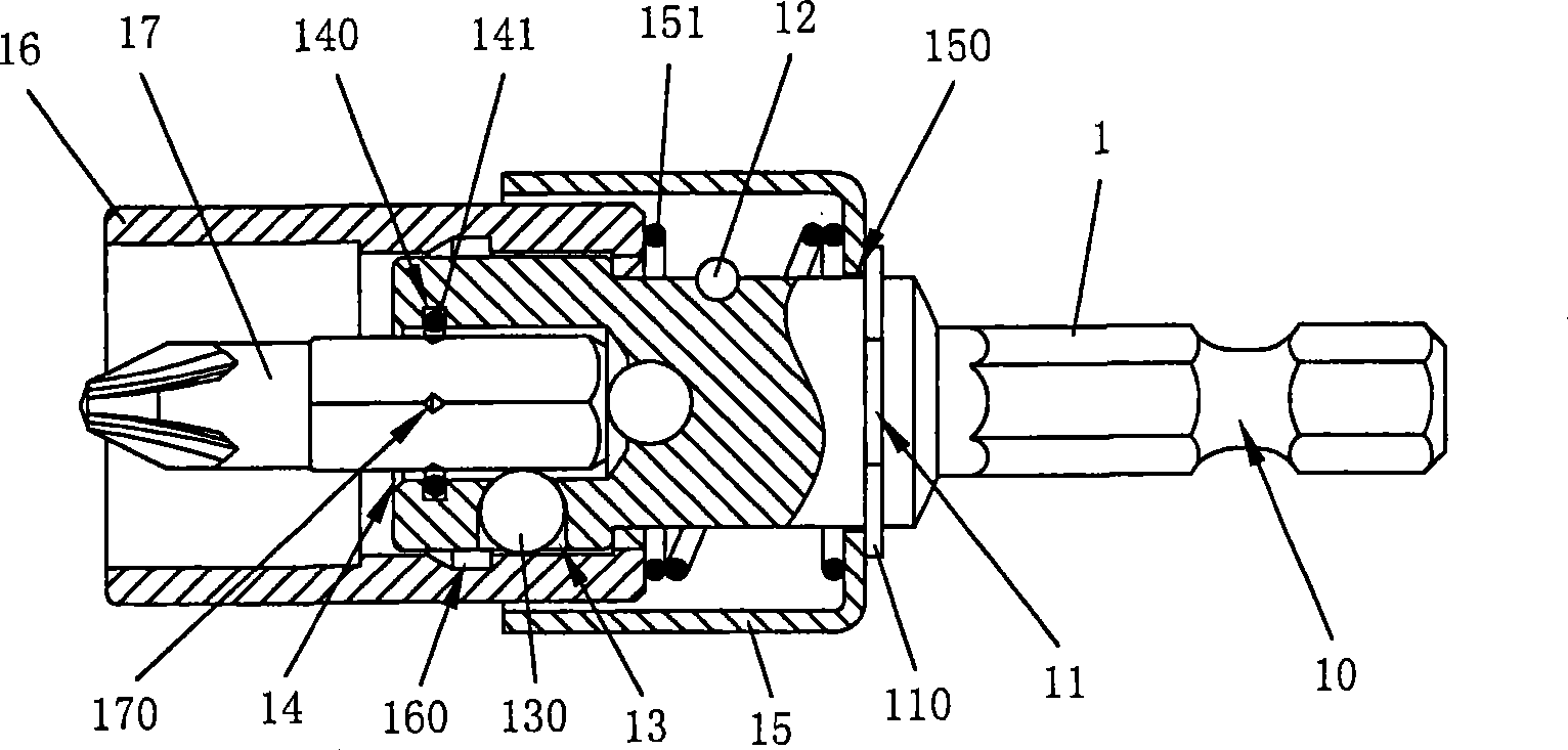
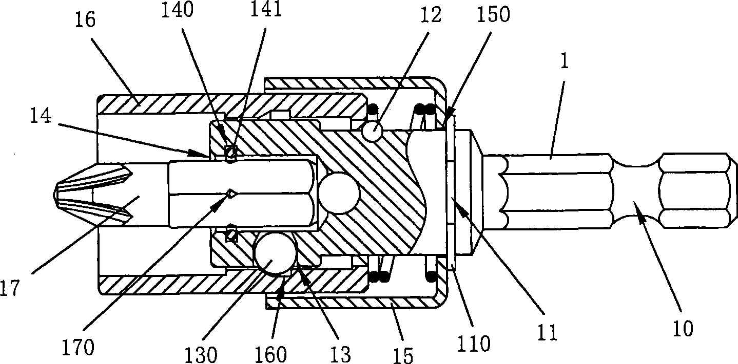
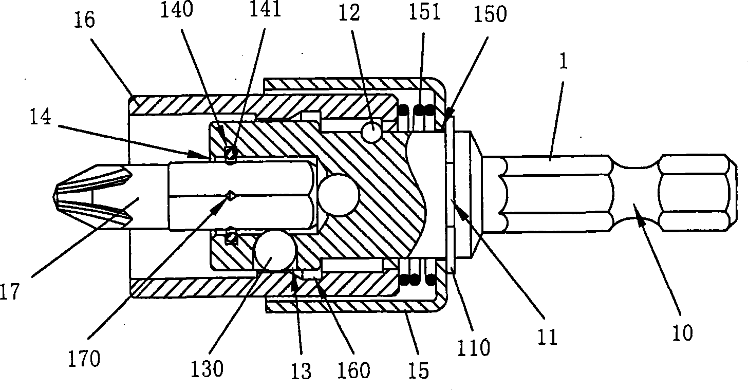
[0047] Such as Figure 4-14 As shown, it is Embodiment 1 of the torque release and clutch structure of the tool screwdriver head of the present invention. This Embodiment 1 includes:

[0048] The connecting rod body 2 is provided with a connecting rod part 20, which can be combined with various known hand tools or electric tools. And establish the E-type buckle groove 21, the E-type buckle 210 can be arranged in the E-type buckle groove 21, and set the washer 211 and the spring 212 on the side of the E-type buckle 210 (as shown in Figures 7-11), and use the washer 211 for the spring One side of 212 abuts against the top, limiting the receding distance of the outer ring 4 . An engaging flange 22 is also provided so that the aforementioned post body 2 has a reverse function. When the screw is pulled out using the reverse function of the post body 2, only the outer ring 4 needs to be compressed backward to keep the screwdriver head at its maximum outer diameter. The elongation ...


PUM


Abstract

The invention provides a torque force releasing and clutching structure for an opener head. A clutch structure is arranged on an extension rod body; the clutch structure is provided with a spring; an internal top ball is arranged at one side of the spring, and is fixed with an internal gasket; due to the internal gasket, the spring and the internal top ball can be limited in a slot of the clutch structure so as to ensure conformability of back and forth tracks of the clutch structure; therefore, when a screw is locked to a set depth, at the moment that the opener head of a hand tool is retracted from a locking slot by a user, the clutch structure is about to push the opener head forward, and leads a torque force release steel ball to release the opener head in time, here, even the hand tool still has remained torque force, the extension rod body can present idling condition so as to maintain standing condition for the opener head. Therefore, the structure can prevent the body or life of the user from being hurt by the remained torque force which returns to the user holding the hand tool through the locked screw, besides ensuring that the remained torque force of the hand tool is prevented from causing improper damage or crash to the locking slot of the screw.

Description

technical field [0001] The present invention relates to a tool screwdriver head torque release and clutch structure, especially a clutch structure on the extension rod body, so that the torque release steel ball can release the screwdriver head in a timely manner, even if the hand tool still has remaining torque, it can only allow the extension rod body In the idling state, the screwdriver head will not rotate. In addition to ensuring that the remaining torque of the hand tool will not cause undue damage and impact to the locking groove of the locked screw, it will also prevent the remaining torque from passing through the fixed screw. Going back to the user who holds the hand tool, the torque release and clutch structure of the tool driver head that causes harm to the user's body or life. Background technique [0002] Known tool screwdriver head clamping structure, such as Figure 1~3 As shown in U.S. Patent No. 4,287,923 and No. 4,753,142, this kind of known structure is p...

Claims


Application Information

Patent Timeline
Patent Type & Authority Applications(China)
IPC IPC(8): B25B23/14B25B23/00
Inventor 陈河田
Owner 陈河田
Why Eureka
Try Eureka