Bicycle rotary crank
A technology for bicycles and cranks, which is applied in the crank structure, vehicle parts, transportation and packaging, etc., and can solve the problems that the pedals cannot be folded
Inactive Publication Date: 2010-12-01
梁满超 +1
View PDF0 Cites 0 Cited by
- Summary
- Abstract
- Description
- Claims
- Application Information
AI Technical Summary
Problems solved by technology
The existing bicycle crank is straight, that is, the pedal hole and the central axis core hole are all on a straight line, and there is no movable core inside. The pedal installed on the crank can only realize the rotation in the front and rear direction, and cannot rotate around the axis. Make folding bicycle pedals less than optimal folding
Method used
View moreImage
Smart ImageViewing Examples

Examples
Embodiment 1
Embodiment 2
Embodiment 3
Login to View More PUM
 Abstract
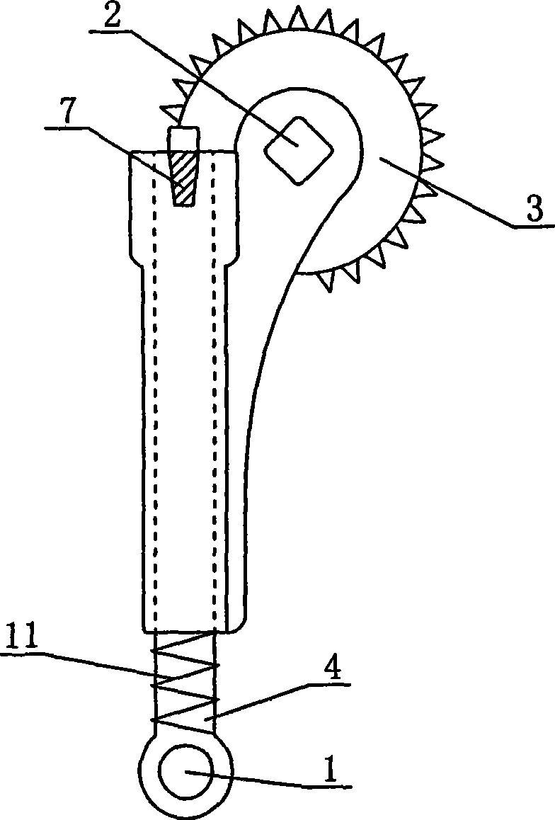
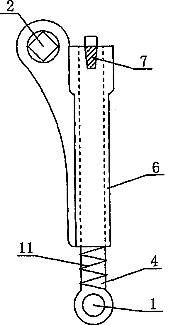
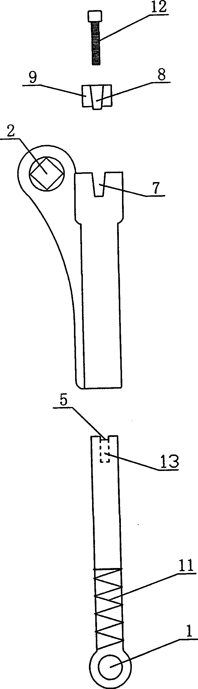
The present invention discloses a bicycle rotary crank which comprises a left crank, a right crank and foot pedal holes and middle shaft core holes which are arranged at the cranks. The middle shaft core hole at the right crank is equipped with a sprocket. The invention is characterized in that the bicycle rotary crank is provided with a movable inner core; the outside of the movable inner core is sleeved with an inner core cover; the foot pedal hole is arranged at one end of the movable inner core; the other end of the movable inner core is provided with an inner neck; one end of the inner slot is equipped with a bayonet which is provided with a block position; the inner core sleeve is provided with a neck which can block the block position; the middle shaft core hole is arranged at the outer side of one end of the neck of the inner core sleeve; the middle shaft core holes are arranged at one side of the neck of the inner core sleeve; the lower ends of the middle shaft core holes is integrated with the inner core sleeve as a whole; and the movable inner core arranged between the foot pedal hole and the inner core sleeve is sleeved with a spring. The bicycle rotary crank can ensure that the foot pedal can rotate forwards and backwards and can also rotate axially around the inner core, thus the foot pedal can be folded towards any direction by 360 degrees.
Description
A bicycle rotating crank Technical field The present invention relates to a rotating crank for a bicycle. Background technique The existing bicycle crank is in the shape of a straight strip, that is, the pedal holes and the central axis core hole are all in a straight line, and there is no movable core inside. The pedals installed on the crank can only rotate in the front and rear direction, and cannot rotate around the axis. The pedals of the folding bicycle cannot be folded in an optimal state. Contents of the invention The object of the present invention is to provide a bicycle rotating crank that enables the pedals to rotate in the forward and backward directions and to rotate around the axis, so that the pedals can be folded in the best state. The technical solution of the present invention is to include a left crank and a right crank, a pedal hole on the crank, a bottom bracket core hole, and a crankset mounted on the bottom bracket core hole of the right crank....
Claims
Login to View More Application Information
Patent Timeline
 Patent Type & Authority Patents(China)
IPC IPC(8): B62M3/00
CPCB62M3/00
Inventor 梁满超张光华
Owner 梁满超