
Locking device with a blocking element

一种锁装置、制动件的技术,应用在建筑锁、车辆部件、运输和包装等方向,能够解决锁装置结构复杂、昂贵等问题,达到简单而可靠设计、提高安全性的效果

Active Publication Date: 2009-03-18
HUF HULSBECK & FURST GMBH & CO KG +1
View PDF1 Cites 16 Cited by
  • Summary
  • Abstract
  • Description
  • Claims
  • Application Information

AI Technical Summary

Problems solved by technology

All in all, this known lock device is complex and expensive

Method used


Image

  • Locking device with a blocking element
  • Locking device with a blocking element
  • Locking device with a blocking element

Examples


Embodiment Construction

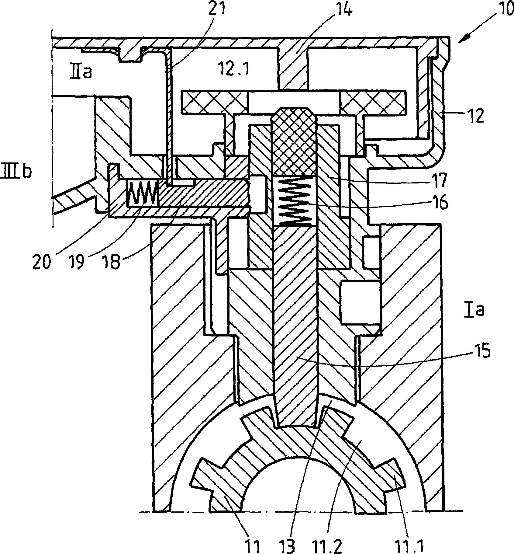
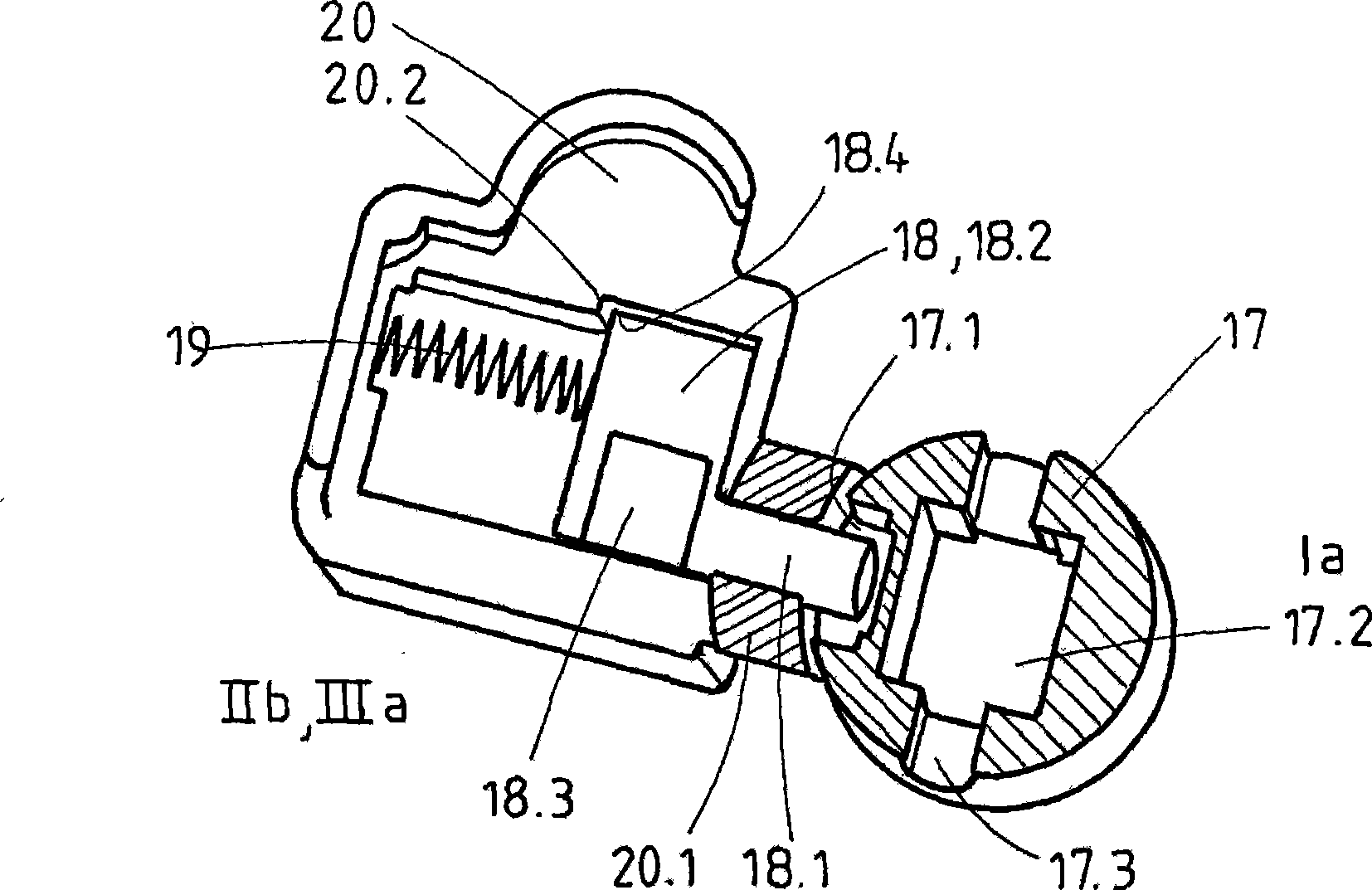
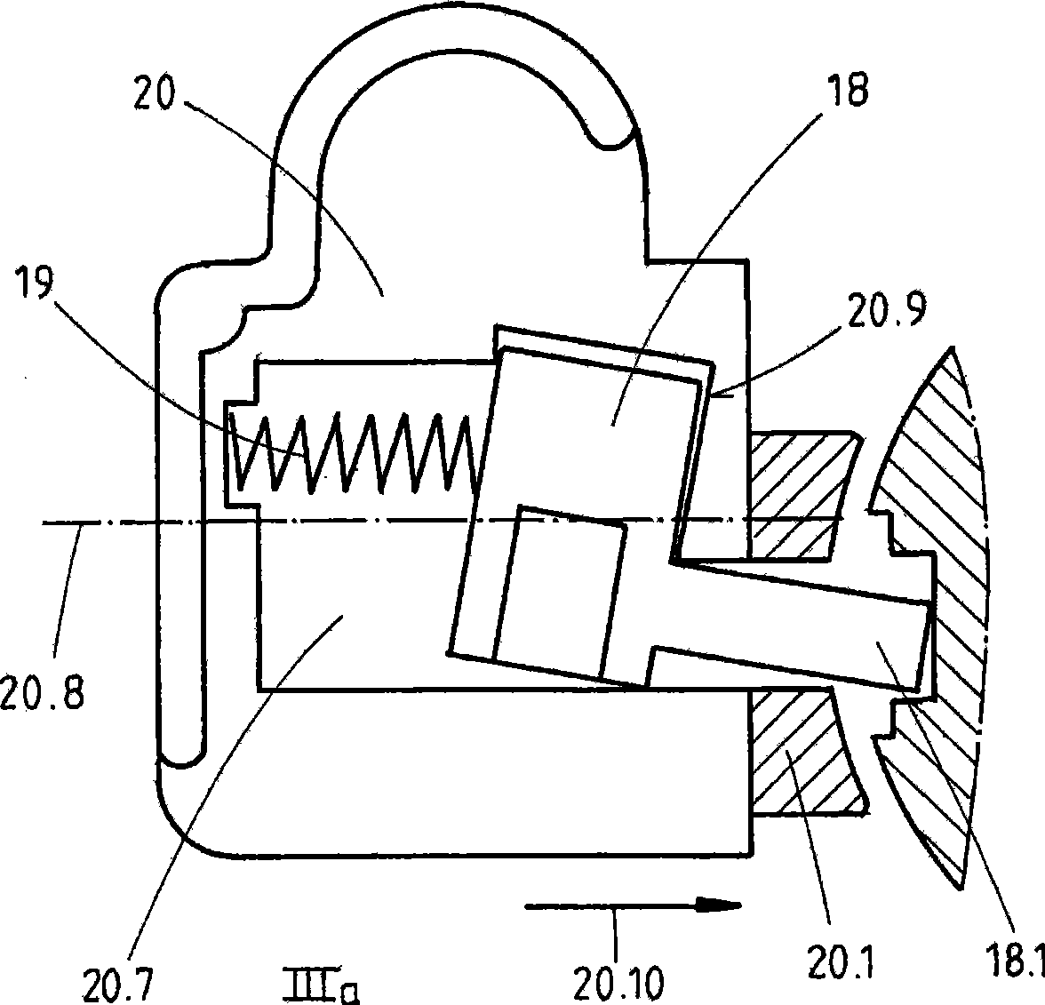
[0093] exist figure 1 The key parts of the lock device 10 are schematically represented in . A component 11 which is essential for operation is blocked here by a lock 15 of the locking device 10 , in this exemplary embodiment the component 11 is designed as a steering lever. For this purpose, the locking element 15 is in the locking position Ia, in which the locking element 15 is mechanically and operatively connected to the component 11 which is essential for operation. Lock piece 15 itself is movably vertically arranged (in figure 1 view) in the lock device 10. The active movement of the lock 15 is produced by the control 17 . In order that the locking element 15 does not have to follow every relative movement of the control element 17 , a spring 16 is arranged between the control element 17 and the locking element 15 . The effect of the spring 16 is to push the locking element 15 into the groove 11.2 of the function-essential part 11 if the locking element 15 is current...


PUM


Abstract

The invention relates to a locking device (10) for the locking and / or unlocking of a component essential (11) for the function of a vehicle with a casing (12), which more preferably serves for the fastening of the locking device (10) to the component essential (11) for the function and a moveable locking member (15), which can assume at least two positions, namely a locking position (Ia), in which the locking member (15) protrudes from the casing (12) through an opening (13) and is actively connected with the component essential (11) for the function and an unlocking position (Ib), in which the locking member (15) is not actively connected with the component essential (11) for the function and an arresting part (18) which in an arresting position (IIIa) arrests the locking member (150 in the locking position (ia) in the event that the locking device (10) is opened without authorization. Accordingly, it is provided according to the invention that the arresting part (18) is positively held in the arresting position (IIIa).

Description

technical field [0001] The invention relates to a locking device for locking and / or unlocking of a component which is essential for operation, more preferably said component is a steering lever or gear lever of a vehicle according to the preamble of claim 1 or similar device. Such a locking device serves to prevent theft of the vehicle by locking components essential for operation in a fixed state with a movable locking member in an active and / or passive manner. Theft of the vehicle and / or unauthorized use of the vehicle can thus be prevented. The lock itself can be directly or indirectly actuated or activated by mechanisms, motors and magnets. Background technique [0002] Patent document EP1182104B1 discloses a prior art of a lock device, wherein, if the outer shell of the lock device is forcefully opened, the lock can be fixed by another safety pin. Here, the safety pin is pushed into the groove of the lock by spring force, thereby actively blocking the lock. In this ...

Claims


Application Information

Patent Timeline
Patent Type & Authority Applications(China)
IPC IPC(8): E05B65/00B60R25/00B60R25/0215
CPCB60R25/02153Y10T70/5664Y10T70/5889Y10T70/5956B60R25/021
Inventor W·特里斯伯格林健次郎渡贯良雄
Owner HUF HULSBECK & FURST GMBH & CO KG
Learn More