Digital-to-analog converter and method for driving the digital-to-analog converter

A technology of digital-to-analog converter and source driver, which is applied in the direction of digital-to-analog converter, analog-to-digital conversion, code conversion, etc., and can solve the problem of size increase

Inactive Publication Date: 2009-03-18
SAMSUNG ELECTRONICS CO LTD
View PDF4 Cites 13 Cited by
  • Summary
  • Abstract
  • Description
  • Claims
  • Application Information

AI Technical Summary

Problems solved by technology

Likewise, LCDs with built-in source drivers also increase in size

Method used


Image

  • Digital-to-analog converter and method for driving the digital-to-analog converter
  • Digital-to-analog converter and method for driving the digital-to-analog converter
  • Digital-to-analog converter and method for driving the digital-to-analog converter

Examples


Embodiment Construction

[0035] Hereinafter, specific embodiments will be described in detail with reference to the accompanying drawings. However, this invention may be embodied in different forms and should not be construed as limited to the embodiments set forth herein. Rather, these embodiments are provided so that this disclosure will be thorough and complete, and will fully convey the scope of the invention to those skilled in the art. In the figures, like reference numerals denote like elements throughout.

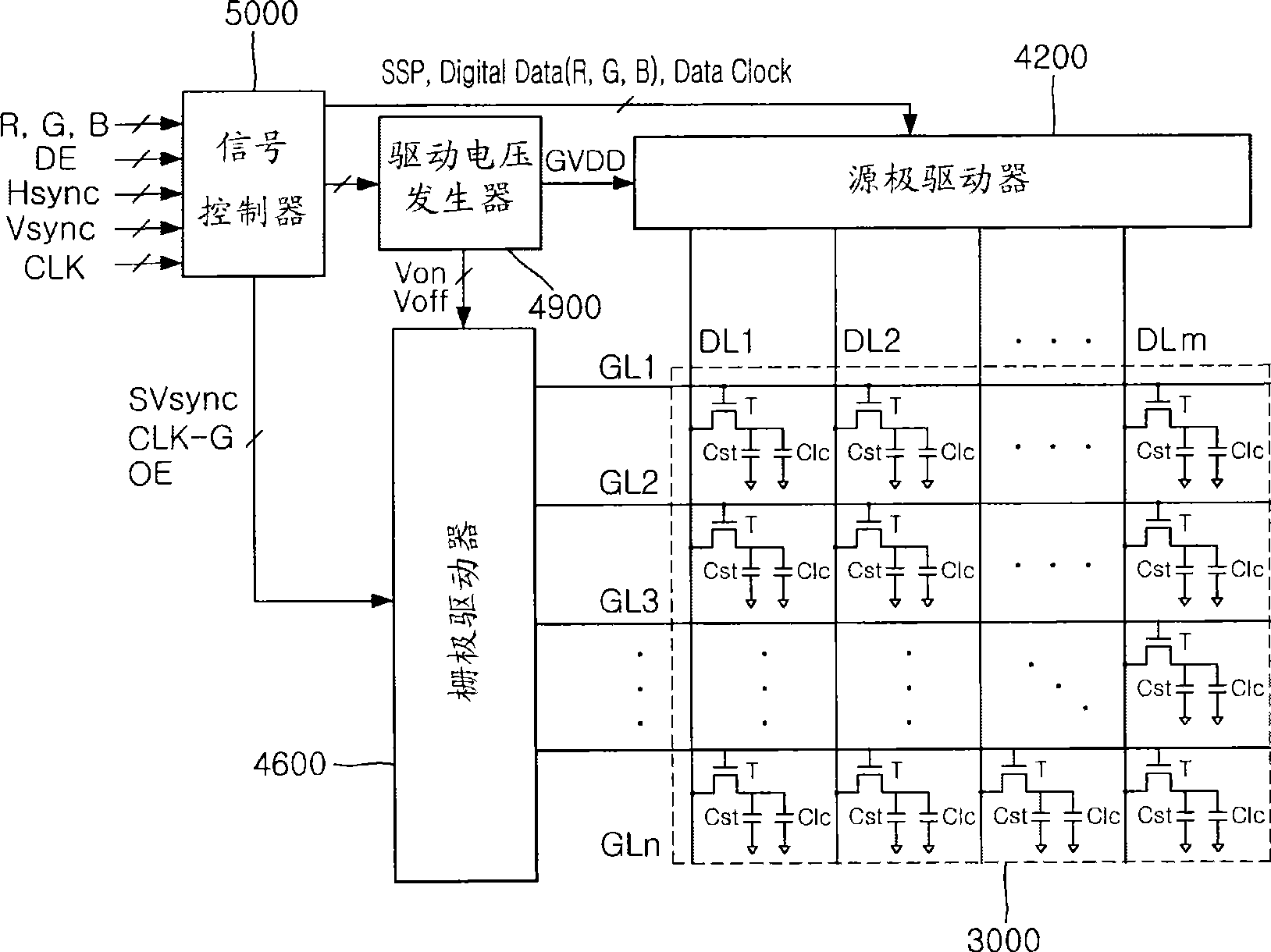
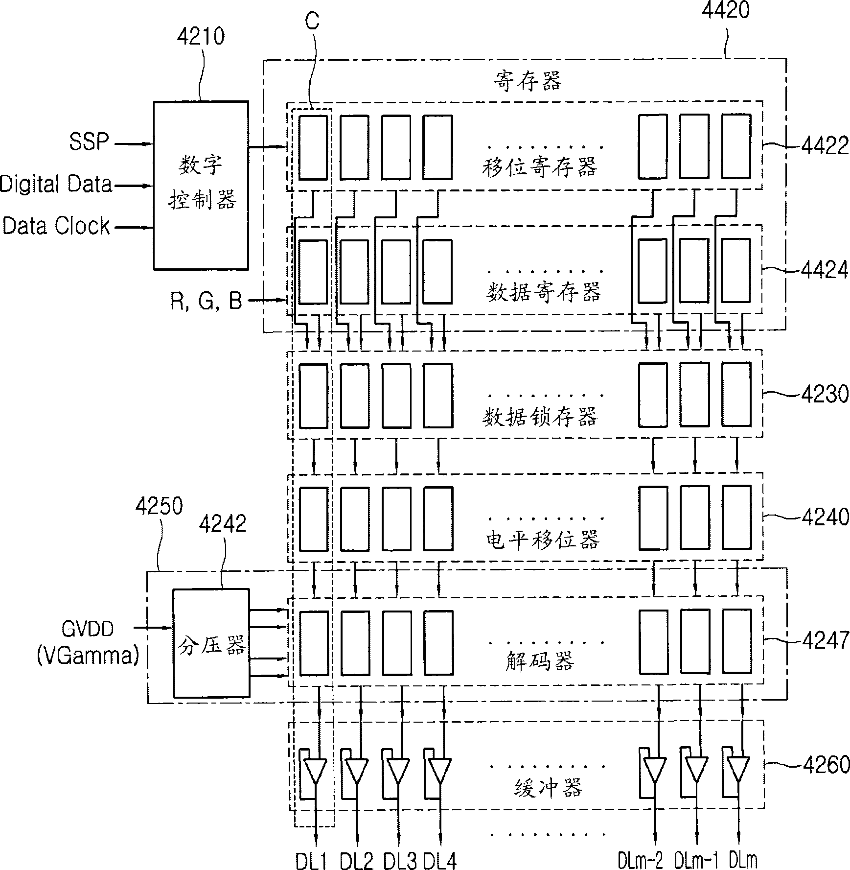
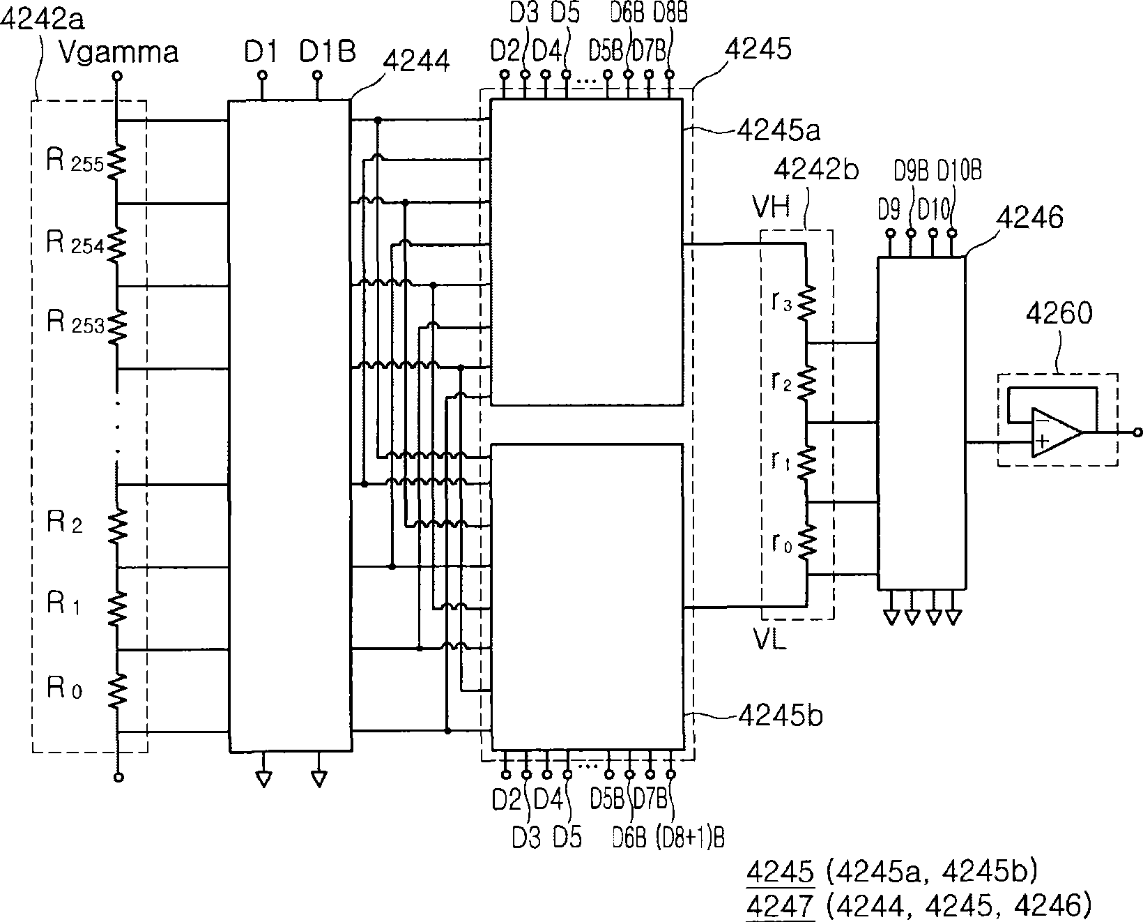
[0036] figure 1 is a block diagram of an LCD according to an exemplary embodiment. figure 2 is a block diagram of the source driver according to this exemplary embodiment. image 3 with Figure 4 is a circuit diagram of a DAC according to this exemplary embodiment. Figure 5 is a block diagram of the pixel data format according to the exemplary embodiment. Image 6 is a flowchart illustrating the operation of the DAC according to this exemplary embodiment. Figure 7A to Figure 7C is...


PUM


Abstract

Provided is a division-type DAC, a method for driving the division-type DAC, a source driver and a display device having the division-type DAC. A decoder of the DAC is divided into a plurality of decoders, so that the number of transistors of each decoder is reduced and the size of the decoder is reduced. Therefore, the DAC with the reduced size, the method for driving the DAC, the source driver and the display device having the DAC with the reduced size can be provided.

Description

[0001] Cross Reference Related Applications [0002] This application claims priority from Korean Patent Application No. 10-2007-0992538 filed with the Korean Intellectual Property Office on September 12, 2007, which is hereby incorporated by reference in its entirety. technical field [0003] The present disclosure relates to a digital-to-analog converter (DAC), a method for driving a DAC, a source driver and a display device including a DAC, and more particularly to a division-type digital-to-analog converter (DAC), a method for driving a division-type DAC Method and source driver and display device including sub-type DAC. Background technique [0004] Recently, there is a market demand for lighter and thinner electric appliances such as monitors, notebook computers, TVs (television sets), and mobile communication terminals. In order to meet such demands, various flat panel display devices have been rapidly developed and promoted as substitutes for cathode ray tubes (CRTs...

Claims


Application Information

Patent Timeline
Patent Type & Authority Applications(China)
IPC IPC(8): H03M1/80G09G3/20G09G3/36
CPCG09G3/3291G09G3/3685G09G2310/027G09G3/2007G09G2320/0673G09G2320/0276G09G3/3648H03M1/76H03M1/68G09G3/36G02F1/133H03M1/66G09G3/20
Inventor 金雅润孙宣圭
Owner SAMSUNG ELECTRONICS CO LTD
Why Eureka
Try Eureka