Cementing granule contact anti-shearing and torsion resistant test device

A technology of cemented particles and testing devices, which is applied in the field of torsion resistance testing devices and shear resistance, and can solve the problems of not being able to measure the mechanical properties of shear and torsion at the contact point of cemented particles

Inactive Publication Date: 2009-03-25
TONGJI UNIV
View PDF0 Cites 18 Cited by
  • Summary
  • Abstract
  • Description
  • Claims
  • Application Information

AI Technical Summary

Problems solved by technology

The existing test results only measure the mechanical properties of the contact points of cemented particles under simple shear and simple torsio

Method used


Image

  • Cementing granule contact anti-shearing and torsion resistant test device
  • Cementing granule contact anti-shearing and torsion resistant test device
  • Cementing granule contact anti-shearing and torsion resistant test device

Examples


Embodiment Construction

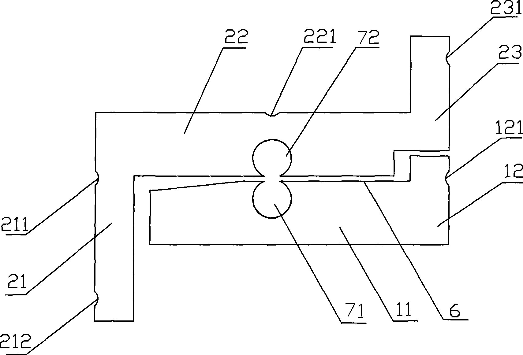
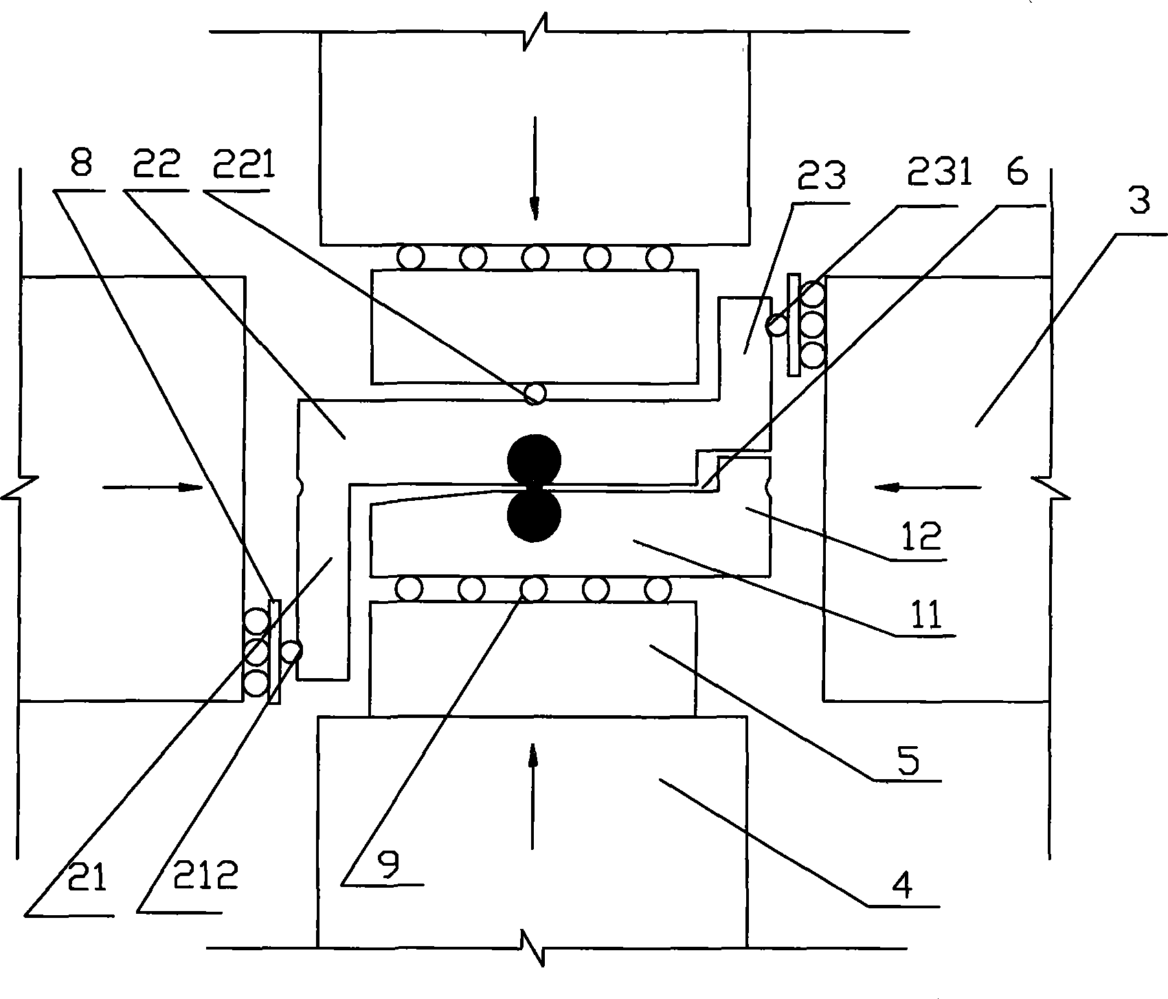
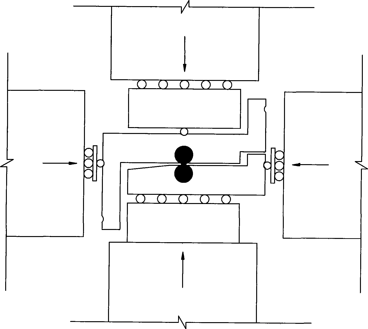
[0015] The cemented particle contact shearing and torsion test device includes an L-shaped part one and a Z-shaped part two. The part one is composed of a horizontal part 11 and a vertical part 12, and the part two is composed of a first vertical part 21, a first horizontal part 22 and The second vertical part 23 is composed of the first horizontal part 22 of the part two and the opposite surface 6 of the horizontal part 11 of the part one in the horizontal direction. Devices 71, 72, the connecting line between their centers is the vertical direction.

[0016] The fixing devices 71, 72 for fixing the cementing particles are respectively provided with a groove 73, 74 which can be put into the cementing particles on the opposite surface 6, and threaded through holes 75, 76 perpendicular to the grooves 73, 74 are set on the part one.

[0017] The second vertical part 23 of the second part and the horizontal part 11 of the first part are provided with gaps in the horizontal direct...


PUM


Abstract

The invention discloses a device for a contact shear resistant and torsion resistant test of cement particles, which comprises an L-shaped part one and a Z-shaped part two, wherein the part one consists of a horizontal part (11) and a vertical part (12), the part two consists of a first vertical part (21), a first horizontal part (22) and a second vertical part (23), opposite surfaces (6) of the first horizontal part (22) of the part two and the horizontal part (11) of the part one is positioned in the horizontal direction, the opposite surfaces (6) of the part two and the part one are respectively provided with fixing devices (71, 72) which can fix the cement particles, and the central connecting line of the opposite surfaces (6) is in the vertical direction. With the structure, the shearing and torsion mechanical characteristics of contact points of the cement particles at different normal pressures can be measured precisely.

Description

technical field [0001] The invention relates to a shear and torsion resistance test device, in particular to a cemented particle contact shear and torsion resistance test device. Background technique [0002] Sand foundations are often encountered in foundation engineering and underground engineering. At present, this kind of engineering design is either based on experience, or numerical simulation is carried out by finite element method. However, the finite element method is a numerical method based on continuum mechanics, which has great defects when used to analyze sandy soil, and the analysis results are often unreliable. A more effective method for analyzing discrete granular materials such as sand is the discrete element method. Discrete element method is a numerical simulation technique based on discontinuous medium mechanics. The key point of the discrete element method is the contact mechanics between particles, that is, the contact constitutive relationship. Th...

Claims


Application Information

Patent Timeline
IPC IPC(8): G01N3/00G01N33/00E02D33/00
Inventor 蒋明镜颜海滨朱合华
Owner TONGJI UNIV
Why Eureka
Try Eureka