Method of cleaning a contact tube of a welding torch, and a welding torch and contact tube

A conductive tube and clean technology, applied in the field of conductive tubes, can solve the problems of unusable production of welding equipment.

Active Publication Date: 2009-04-15
FRONIUS INTERNATIONAL GMBH
View PDF0 Cites 4 Cited by
  • Summary
  • Abstract
  • Description
  • Claims
  • Application Information

AI Technical Summary

Problems solved by technology

In order to remove worn conductive tubes and install new conductive tubes, the welding equipment must be switched off and cannot be used for production

Method used


Image

  • Method of cleaning a contact tube of a welding torch, and a welding torch and contact tube
  • Method of cleaning a contact tube of a welding torch, and a welding torch and contact tube
  • Method of cleaning a contact tube of a welding torch, and a welding torch and contact tube

Examples


Embodiment Construction

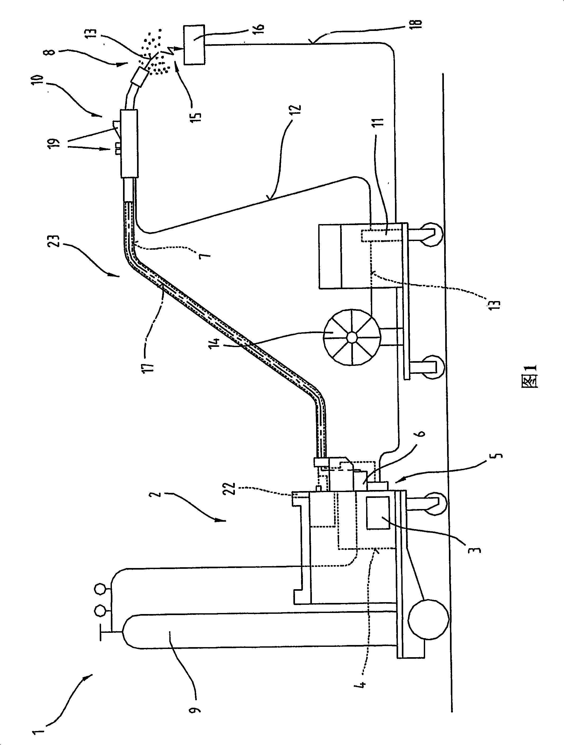
[0048] In FIG. 1 , a welding device 1 is shown for most different welding processes, such as MIG / MAG welding and / or WIG / TIG welding or electrode welding, twin wire / tandem welding, etc.

[0049] The welding device 1 comprises a current source 2 with a power element 3 , a control unit 4 and switching means 5 associated with the power element 3 and / or the control unit 4 . The switching member 5 and / or the control unit 4 are connected to a control valve 6 which is followed by a protective gas 8 such as CO 2 A supply line 7 of , helium or argon is arranged between the gas reservoir 9 and the welding torch 10 .

[0050] Furthermore, a wire feeder 11 usually used for MIG / MAG welding can be activated by means of the control unit 4 , and welding wire 13 is fed by means of a reel 14 via a supply line 12 into the region of the welding torch 10 . The wire feeder 11 can be designed as an accessory or integrated into the welding device 1 .

[0051] The current for establishing the arc 15 ...


PUM

PropertyMeasurementUnit
lengthaaaaaaaaaa

Abstract

The invention relates to a method of cleaning a contact tube (20) of a welding torch (10), via which contact tube (20) a welding wire (13) moved to the welding torch (10) from a wire reel (14) or a wire drum via a wire delivery device (11) is supplied with electrical energy, and to a welding unit (1) and a contact tube (20) for the welding torch (10) of such a welding unit (1). To prolong the service life of a contact tube (20) of a welding torch (10), provision is made according to the invention for the welding wire (13) to be moved back at least once in the direction of the wire reel (14) or wire drum until the end (27) of the welding wire (13) lies at least within the length (36) of the contact tube (20), and for the welding wire (13) to then be moved forward again, in particular into the initial position again.

Description

technical field [0001] The present invention relates to a method of cleaning the contact tube of a welding torch through which electrical energy is supplied to the welding wire which is moved by means of a reel or drum via a wire feeder to the welding torch. [0002] Furthermore, the invention relates to a welding device having a current source and a welding torch comprising a conductive tube for supplying electrical energy to a welding wire which is moved to the welding torch by means of a wire reel via a wire feeder. [0003] Finally, the invention relates to a conductive tube for a welding torch of a welding device as described above. Background technique [0004] The invention relates to a welding method in which the welding wire is fed into the region of the welding torch by means of a spool or drum. Here, an electric arc burns between the welding wire and the workpieces to be joined. In order to establish the electrical contact of the welding wire, the welding wire i...

Claims


Application Information

Patent Timeline
Patent Type & Authority Applications(China)
IPC IPC(8): B23K9/29
CPCB08B9/021B23K9/124B23K9/328
Inventor M·吕尔诺斯H·斯陶弗尔
Owner FRONIUS INTERNATIONAL GMBH
Why Eureka
Try Eureka