Binder, and file

A technology of utensils and binding rods, which is applied to file folders, printing, etc., to achieve the effect of simplifying operations and improving the convenience of use

Inactive Publication Date: 2009-04-22
KOKUYO CO LTD
View PDF2 Cites 2 Cited by
  • Summary
  • Abstract
  • Description
  • Claims
  • Application Information

AI Technical Summary

Problems solved by technology

[0008] Also, in order to lift the handle, the entire folder may also be lifted
At this time, you must hold the operating handle with one hand, and press the cover of the folder with the other hand, that is, you must use both hands to operate.

Method used


Image

  • Binder, and file
  • Binder, and file
  • Binder, and file

Examples


Embodiment Construction

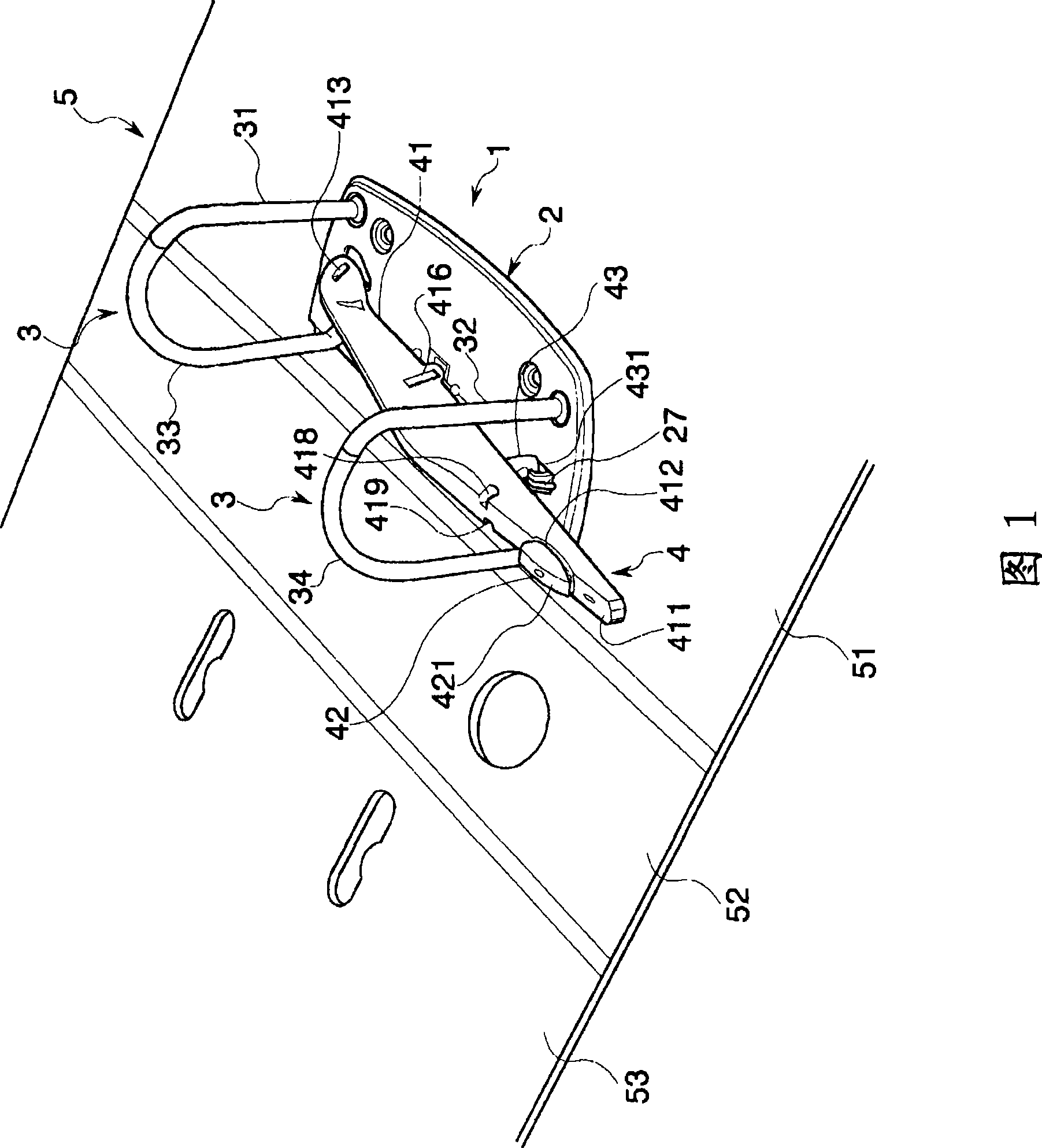
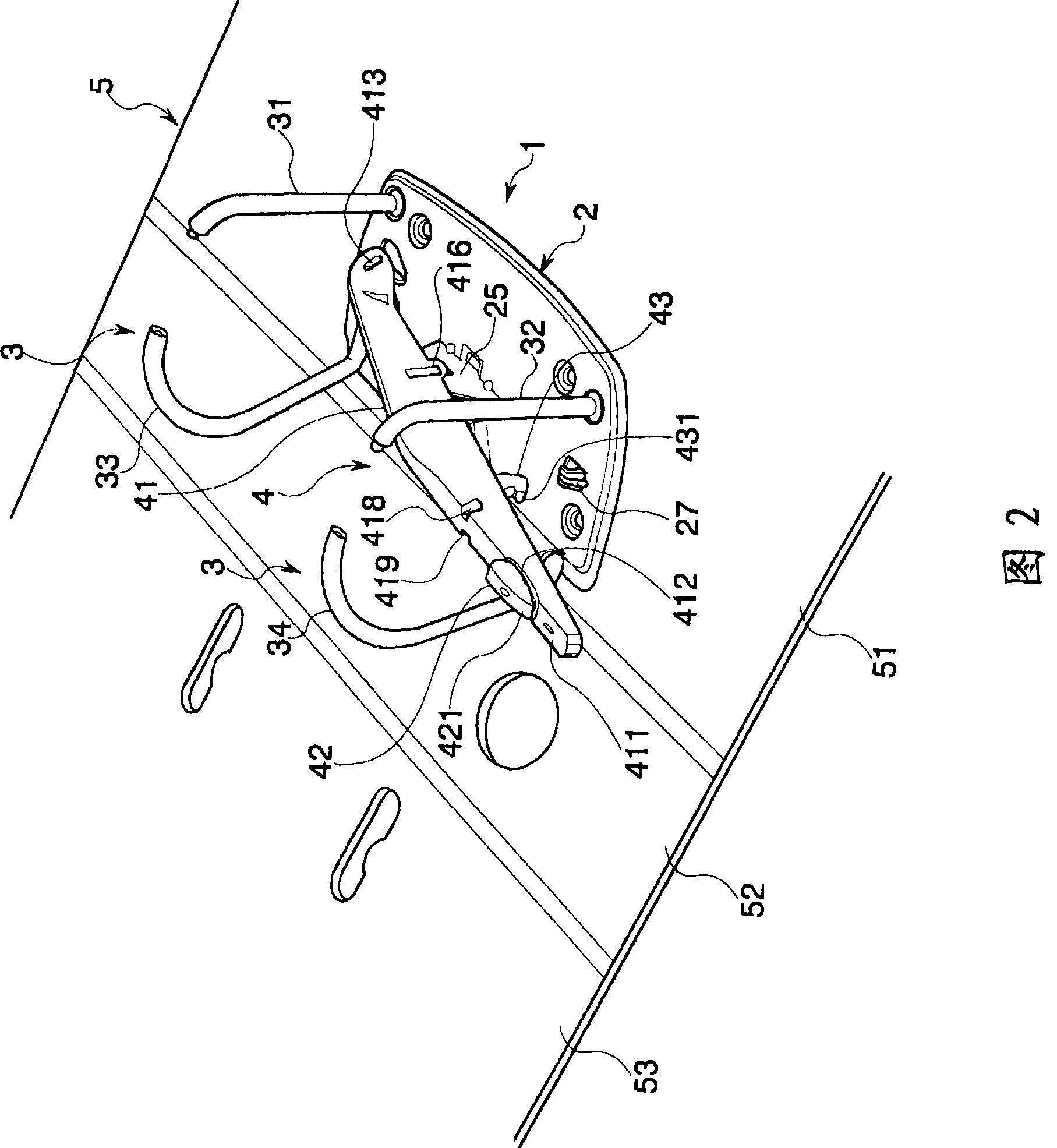
[0057]Hereinafter, embodiments of the present invention will be described with reference to the drawings. For simplification of description, here, the rotation center side of the operating handle 4, 4x is defined as the front, and the side of the operation part 41, 41x is defined as the rear. A folder using the binding tool 1 of this embodiment is shown in FIGS. 1 and 2 . In this folder, a binding tool 1 for binding a plurality of sheets of paper is attached to the inner surface of a cover 5 .

[0058] The cover 5 is, for example, a resin molded product, and has a back cover 51 , a back cover 52 connected to the side edge of the back cover 51 by a hinge, and a front cover 53 connected to the side edge of the back cover 52 by a hinge. In the example shown in the figure, the bookbinding tool 1 is attached to the inner surface of the back cover 51 of the cover 5 and beside the back cover 52 .

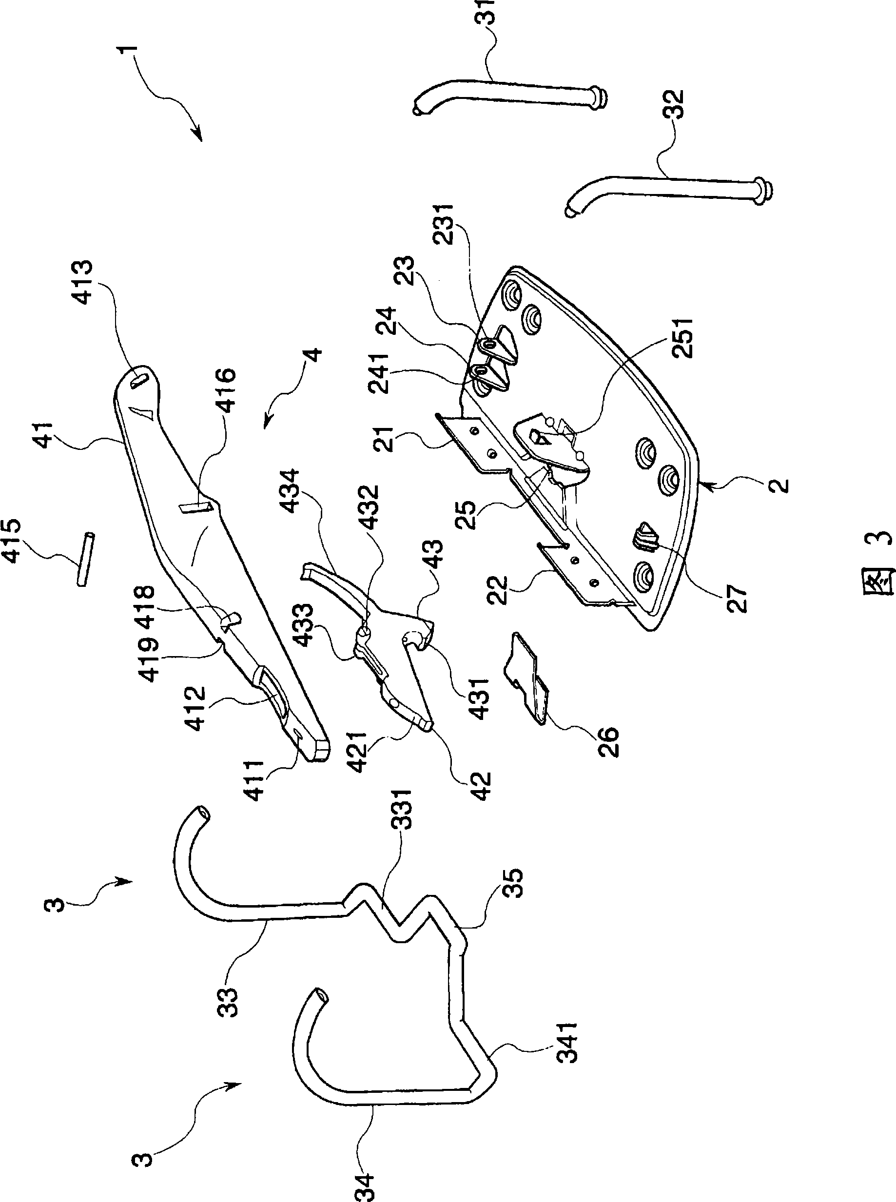
[0059] As shown in Figures 3 to 8, the binding tool 1 is formed with a base 2 engage...


PUM


Abstract

The invention relates to a binder and a file for simplifying operation when opening a binding pole. Provided is a binder (1), which is constituted to comprise a first operation portion (41) adapted to be displaced, in response to a pushing operation, from an unlock position, at which a binding lever (3) is opened, to a lock position, at which the binding lever (3) is closed, a holding mechanism (43) for holding the first operation portion (41) having reached the lock position, at this lock position, and a second operation portion (42) adapted to release, in response to the pushing operation, the holding of the first operation portion (41) by the holding mechanism.

Description

technical field [0001] The present invention relates to a binder for folders for binding multiple sheets of paper. Background technique [0002] There are various folders for binding paper. For example, the following patent documents disclose a document file in which a pair of binding rod elements that rotate relative to each other form an annular body for binding and fixing sheets of paper. An operating handle is provided in this folder, and the closed binding rod can be opened by lifting the operating handle, and the opened binding rod can be closed by pressing the operating handle. [0003] More specifically, the binding rod has a fixed binding rod element standing on the base and a movable binding rod element rotatably supported on the base, and the top ends of the two binding rod elements can be mutually opened and closed. The movable binding bar element is spring loaded in a direction away from the fixed binding bar element. A crankshaft protruding in a direction in...

Claims


Application Information

Patent Timeline
Patent Type & Authority Applications(China)
IPC IPC(8): B42F13/26B42F13/36B42F13/00
CPCB42F13/24
Inventor 秋山弘昭
Owner KOKUYO CO LTD
Why Eureka
Try Eureka