
Electronic device

一种电子设备、设备的技术,应用在光学、仪器、放映装置等方向,能够解决不能配置、阻碍投影机小型化、难以有效利用壳体内部空间等问题,达到降低丢失、实现便利性、便利性提高的效果

Inactive Publication Date: 2009-05-13
SEIKO EPSON CORP
View PDF1 Cites 1 Cited by
  • Summary
  • Abstract
  • Description
  • Claims
  • Application Information

AI Technical Summary

Problems solved by technology

[0007] However, in the technique described in Patent Document 1, it is necessary to secure a space for installing a protrusion inside the housing and a space for the leg to enter the interior of the housing via the protrusion.
Moreover, other structural components cannot be arranged in such a space, so it is difficult to effectively use the space inside the housing.
In addition, since the above-mentioned space needs to be ensured inside the casing, miniaturization of the projector is hindered.

Method used


Image

  • Electronic device
  • Electronic device
  • Electronic device

Examples


Embodiment Construction

[0060] Embodiments of the present invention will be described below based on the drawings.

[0061] [main structure of projector]

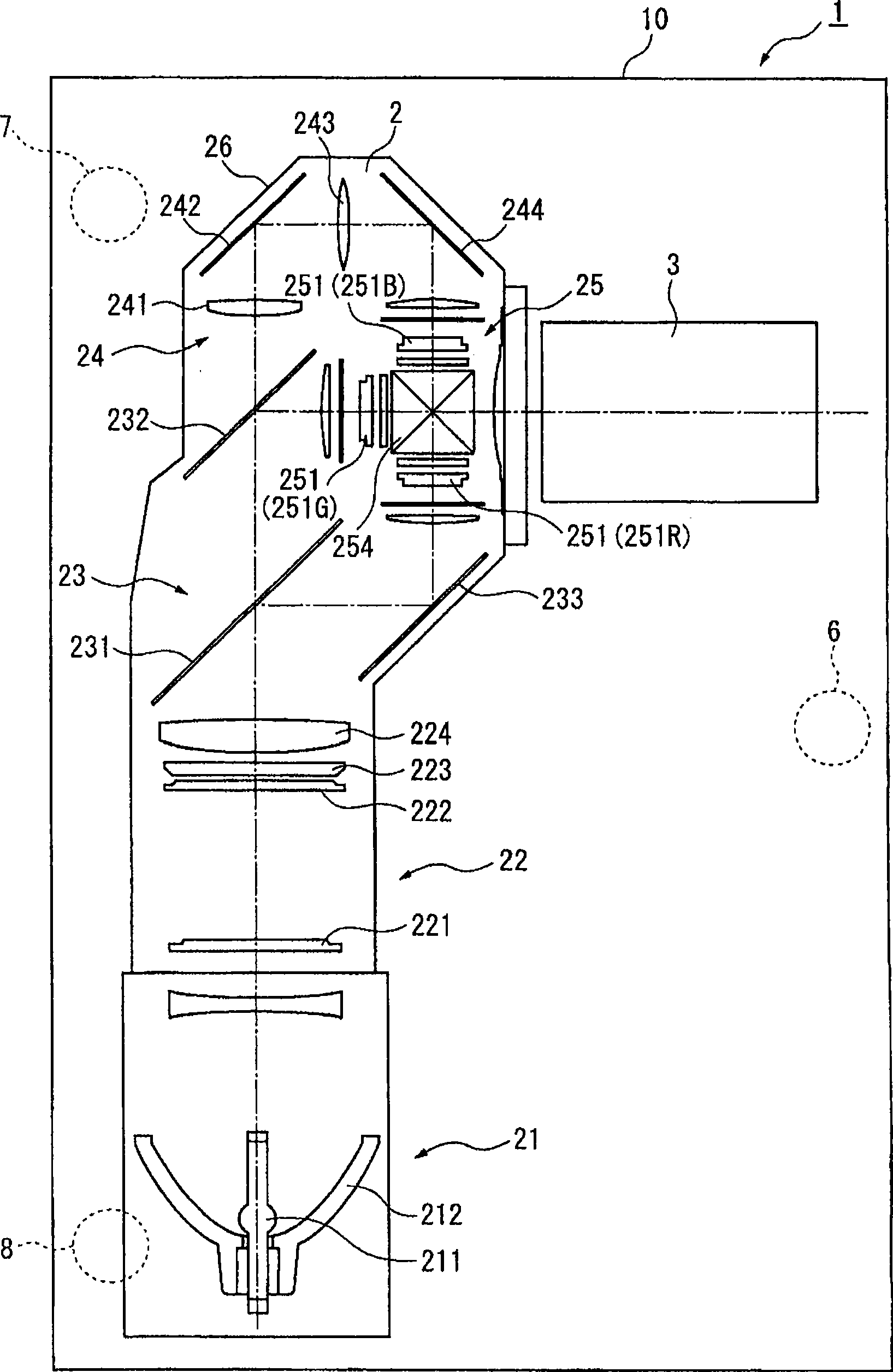
[0062] figure 1 It is a plan view schematically showing a schematic configuration of a projector as an electronic device according to the present embodiment.

[0063] The projector modulates a light beam emitted from a light source based on image information to form a color image (image light), and projects the color image in an enlarged manner on a screen (not shown in the figure) or the like.

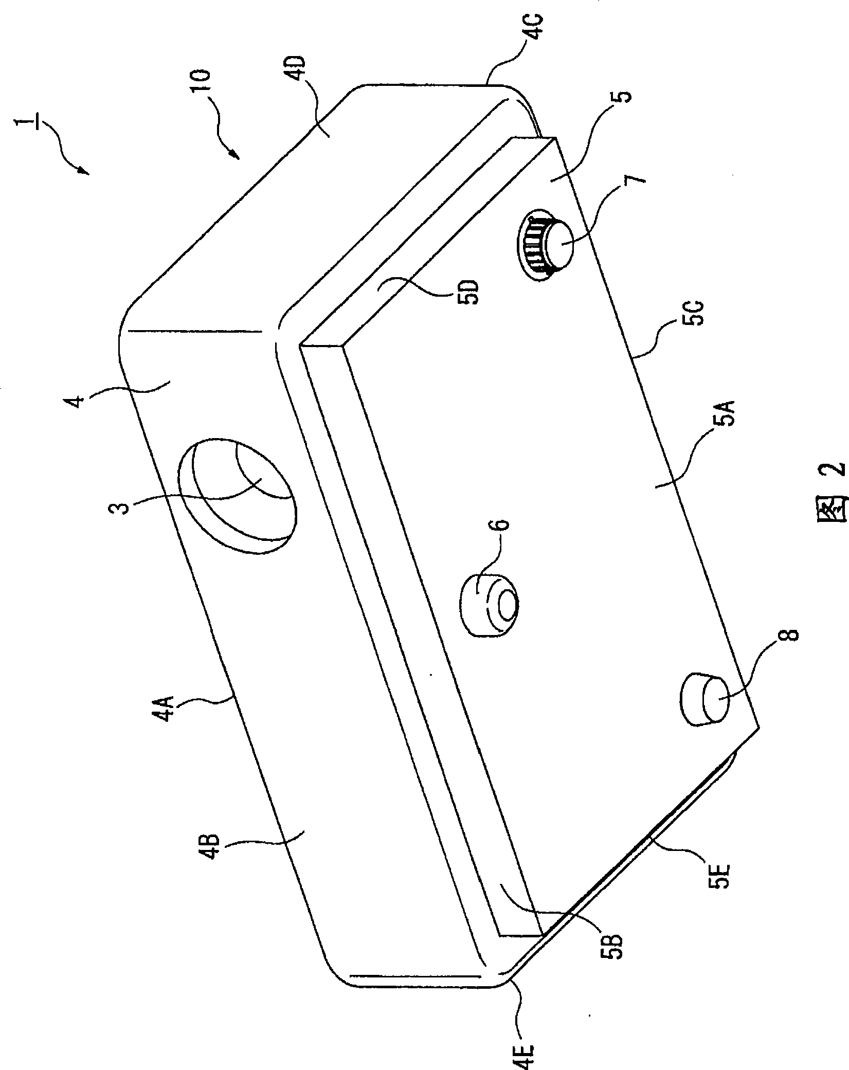
[0064] Such as figure 1As shown, the projector 1 includes: an optical unit 2, a projection lens 3 as a projection optical device, a casing 10 for accommodating these equipment main bodies and constituting an outer package, and a front foot 6 and a foot 7 arranged on the outer surface of the casing 10. And fixed pin 8 etc.

[0065] In addition, in figure 1 Although the specific illustration is omitted, in the housing 10, in the space other than the op...


PUM


Abstract

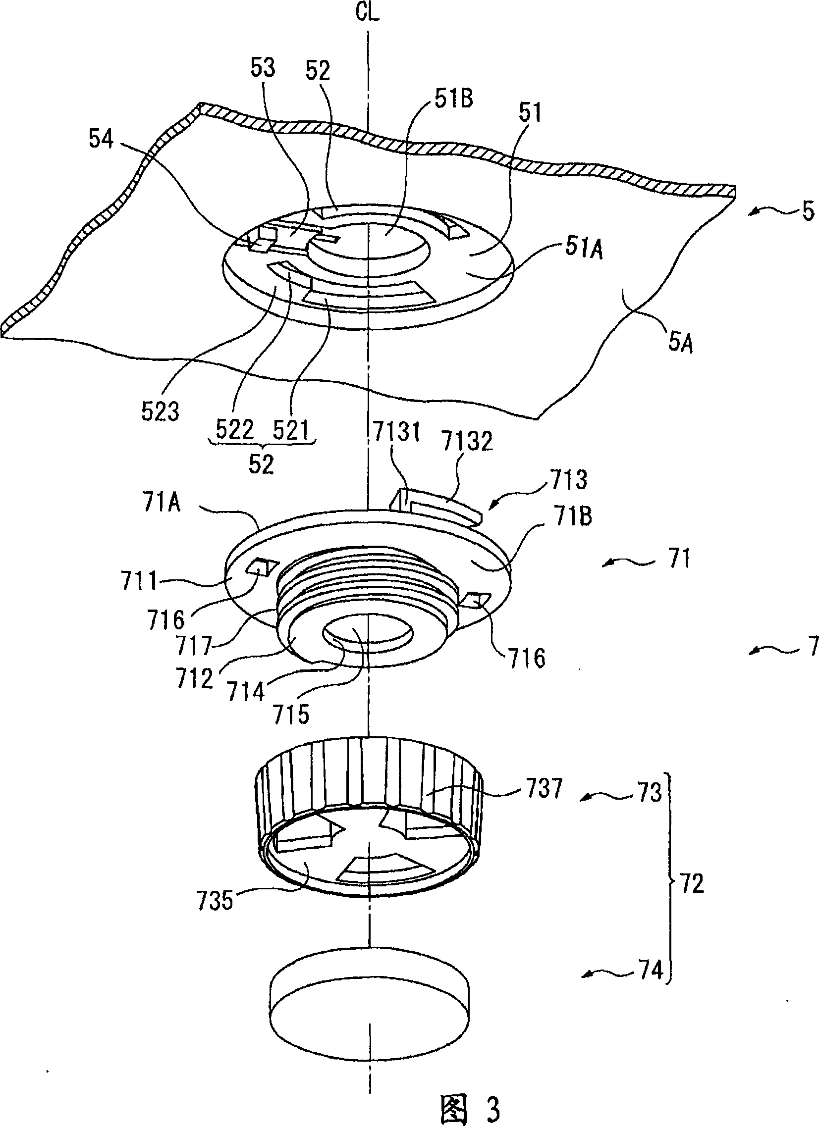
An electronic device comprises the following components: a casing (10), and a foot part (7) which contacts the installation surface provided with the casing (10) and changes the projection length L projected from the outer surface of casing (10). The foot part (7) comprises the following components: a foot part body (72) which contacts the installation surface, and a supporting component (71) which is installed to project from the external surface of casing (10) and to support the foot part body (72). The supporting component (71) comprises the following components: a base part (711) which is installed on the external surface of casing (10), and a projection (712) which projects from the base part (711) and is formed with thread groove (717) on the external peripheral surface. The foot part body (72) is provided with an insertion hole (734) inserted into the projection (712) at one end. The inner peripheral surface of insertion hole (734) is formed with screw thread (731) which is jointed with the thread groove (717) through screw connection. The projection length L is changed through changing the screw joint state to the supporting component (71).

Description

technical field [0001] The present invention relates to an electronic device, which includes: a case for accommodating a main body of the device, and a leg portion that contacts an installation surface provided with the case and changes the protruding length from the outside of the case. Background technique [0002] Conventionally, there is known a projector in which a light beam from a light source is modulated according to image information by a light modulation device, and the modulated image light is projected onto a screen or the like disposed on the front side. [0003] However, in such a projector, when the installed installation surface is inclined, the projected image is also inclined. [0004] Therefore, a technique has been proposed that adjusts the inclination of a projected image by changing the protruding length of the legs protruding from the projector casing to change the posture of the projector (for example, refer to Patent Document 1). [0005] In the te...

Claims


Application Information

Patent Timeline
Patent Type & Authority Applications(China)
IPC IPC(8): G03B21/14G03B21/00H05K5/02
CPCG03B21/14G03B21/145
Inventor 黑田明寿
Owner SEIKO EPSON CORP
Learn More