Minitype electric lockset

An electronic and miniature technology, applied in the application of electric locks, building locks, locks, etc., can solve the problems of inconvenient management of IC cards and magnetic cards, inability to directly install them in power cabinets, and restrict the general promotion of electronic locks. Convenient and effective management, high anti-theft performance, reliable locking effect

Inactive Publication Date: 2009-05-20
HEFEI TIANZHI TECH DEV
View PDF0 Cites 6 Cited by
  • Summary
  • Abstract
  • Description
  • Claims
  • Application Information

AI Technical Summary

Problems solved by technology

[0002] The locks in the prior art are generally traditional mechanical locks assembled from mechanical parts. The disadvantage is that as long as the mechanical lock key with the same size and shape can be used to unlock the lock, its security and anti-theft performance are poor, so it is not suitable for It is used in places with high requirements for confidentiality and anti-theft performance. In addition, there are many places where locks are needed in life and work. Since one key can only open one lock, we need to carry a bunch of keys with us. You also need to find one of the keys in a bunch, which is very inconvenient to use
In addition, there are IC card locks and magnetic card locks. Although the security is improved, it is very inconvenient to use IC cards and magnetic card management for decentralized door locks.
However, the size of the existing electronic locks is too large to be directly installed in the lock box of the power cabinet, which limits the popularization of electronic locks in the power system

Method used


Image

  • Minitype electric lockset
  • Minitype electric lockset
  • Minitype electric lockset

Examples


Embodiment Construction

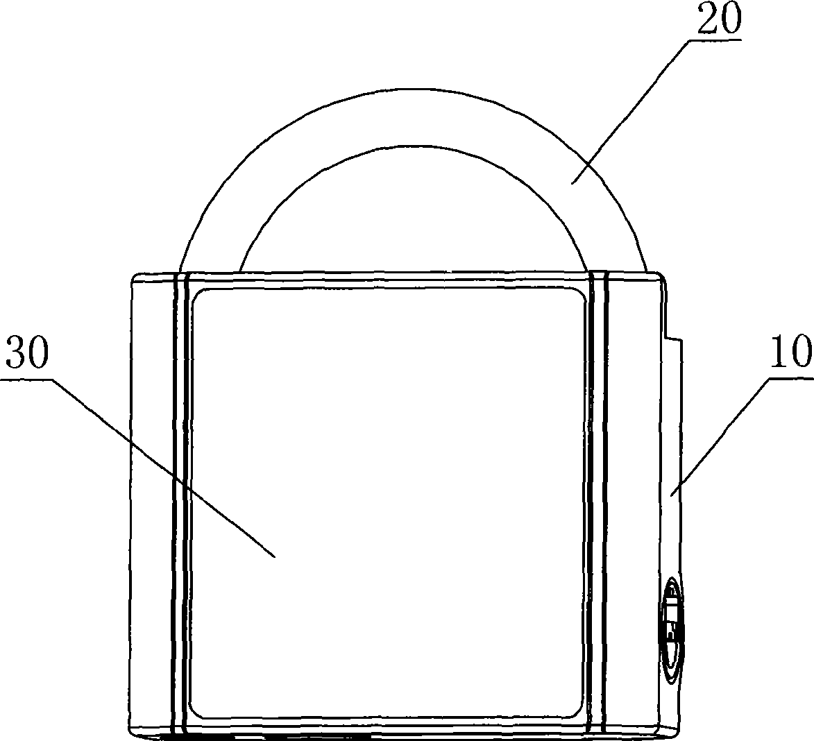
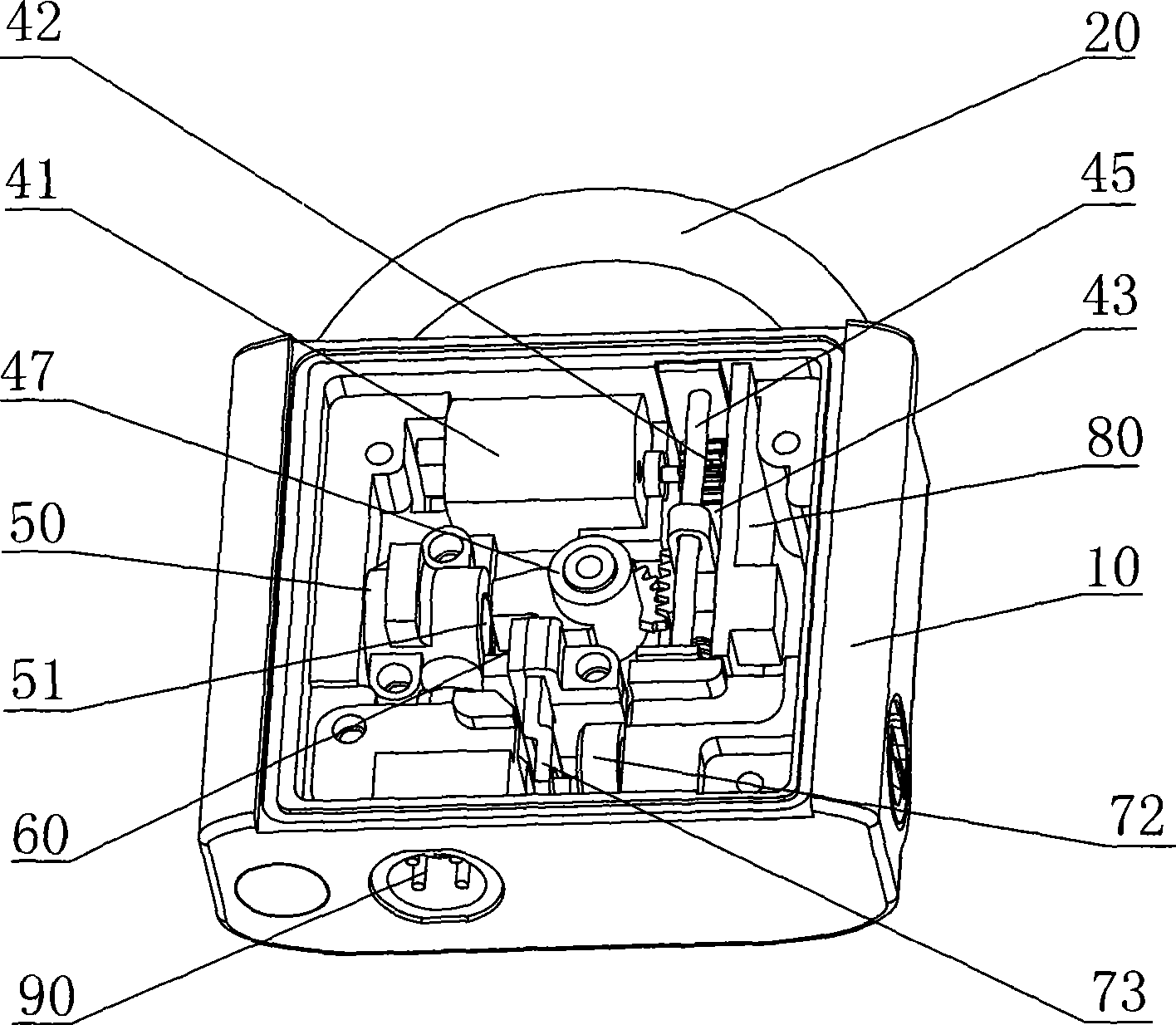
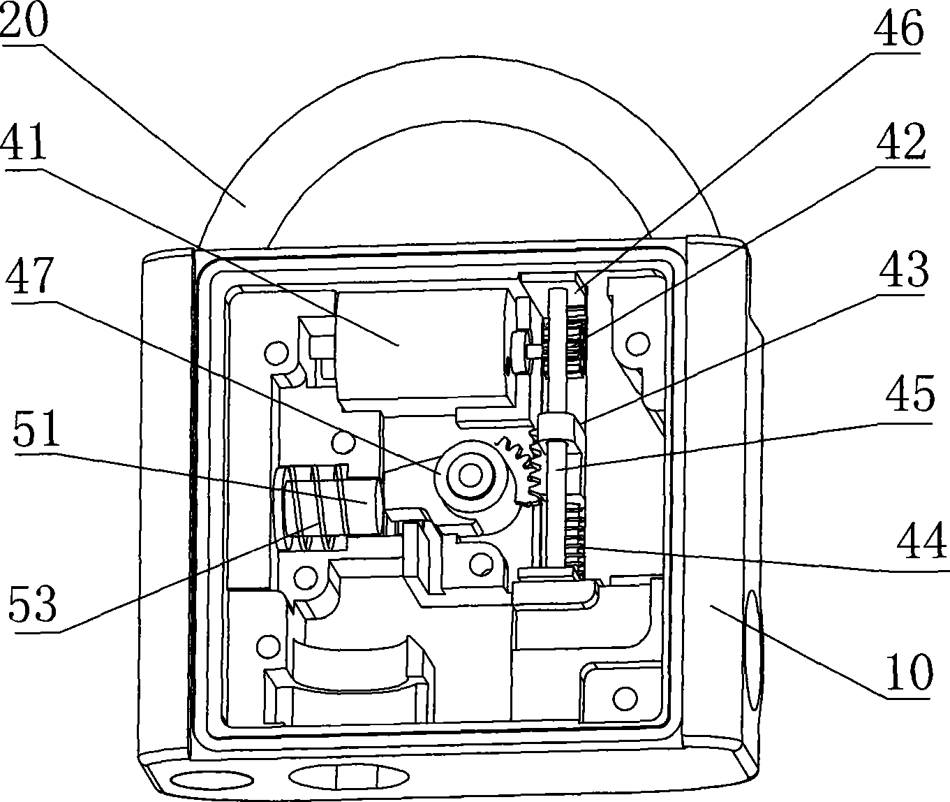
[0015] A miniature electronic lockset is composed of a lock body 10 and a U-shaped lock beam 20. A cavity is provided on the lock body 10. A cover 30 is arranged at the opening of the cavity. The U-shaped lock beam 20 and the lock body 10, a waterproof sealing ring is provided between the lock body 10 and the cover body 30, and the part of the cavity of the lock body 10 that communicates with the outside world is treated with waterproof sealing. There is an electronic locking mechanism in the area surrounded by the cover body 30 and the lock body 10. The electronic locking mechanism includes an electronic drive mechanism 40. The electronic drive mechanism 40 includes a motor 41 connected to the drive signal output end of the control circuit. The motor 41 adopts a direct current The motor, the motor 41 drives the locking plug mechanism 50 and the U-shaped lock beam 20 to be in two positions of separation and unlocking or inlaying and locking. The drive signal input end of the co...


PUM


Abstract

The invention discloses a micro electronic lockset which consists of a lock body and a U-shaped lock bridge. The lock body is provided with a cavity part, the opening part of which is provided with a cover body; an area enclosed by the cover body and the lock body is provided with an electronic locking mechanism which comprises an electronic driving mechanism; a driving signal input end of a control circuit is electrically connected with a data interface arranged on the lock body; and the electronic driving mechanism comprises a motor connected with the driving signal output end of the control circuit and the lock mechanism and the U-shaped lock bridge are driven by the motor to be in a separation and unlocking state or a matching and locking state by embedding. The lockset is matched with a handset for use, thus being convenient for unlocking and reliable in locking with higher antitheft performance; the handset is convenient for managing dispersive gate locks; the micro electronic lockset does not need power supply, therefore, the power consumption is lower; and when the lock is opened or closed, operational data is respectively recorded in memory chips of the handset and the microelectronic lockset, thus being more convenient and effective in managing the gate opening record.

Description

technical field [0001] The invention relates to a miniature electronic lock. Background technique [0002] The locks in the prior art are generally traditional mechanical locks assembled from mechanical parts. The disadvantage is that as long as the mechanical lock key with the same size and shape can be used to unlock the lock, its security and anti-theft performance are poor, so it is not suitable for It is used in places with high requirements for confidentiality and anti-theft performance. In addition, there are many places where locks are needed in life and work. Since one key can only open one lock, we need to carry a bunch of keys with us. It is also necessary to look for one of them in a bunch of keys, which is very inconvenient to use. In addition, there are IC card locks and magnetic card locks. Although the safety is improved, it is very inconvenient to manage scattered door locks with IC cards and magnetic cards. However, the size of the existing electronic loc...

Claims


Application Information

Patent Timeline
IPC IPC(8): E05B49/00E05B47/06
Inventor 赵宁罗晓革程力董明云
Owner HEFEI TIANZHI TECH DEV
Why Eureka
Try Eureka