
Apparatus for controlling die cushion of press machine

A buffer mechanism and mold technology, applied in digital control, program control, electrical program control, etc., can solve problems such as inability to accurately implement bottom dead center locking, bottom dead center position deviation, etc.

Active Publication Date: 2010-12-08
KOMATSU SANKI
View PDF5 Cites 1 Cited by
  • Summary
  • Abstract
  • Description
  • Claims
  • Application Information

AI Technical Summary

Problems solved by technology

That is, there is a problem that the position of the actual bottom dead center of the slider also deviates due to plate thickness errors or machining errors of the workpiece. If the target position is set to one point, the target position and the actual bottom dead center position will also deviate, so that the bottom dead center lock cannot be accurately implemented

Method used


Image

  • Apparatus for controlling die cushion of press machine
  • Apparatus for controlling die cushion of press machine
  • Apparatus for controlling die cushion of press machine

Examples


Embodiment Construction

[0052] Next, specific embodiments of the mold cushioning mechanism control device of the present invention will be described with reference to the drawings.

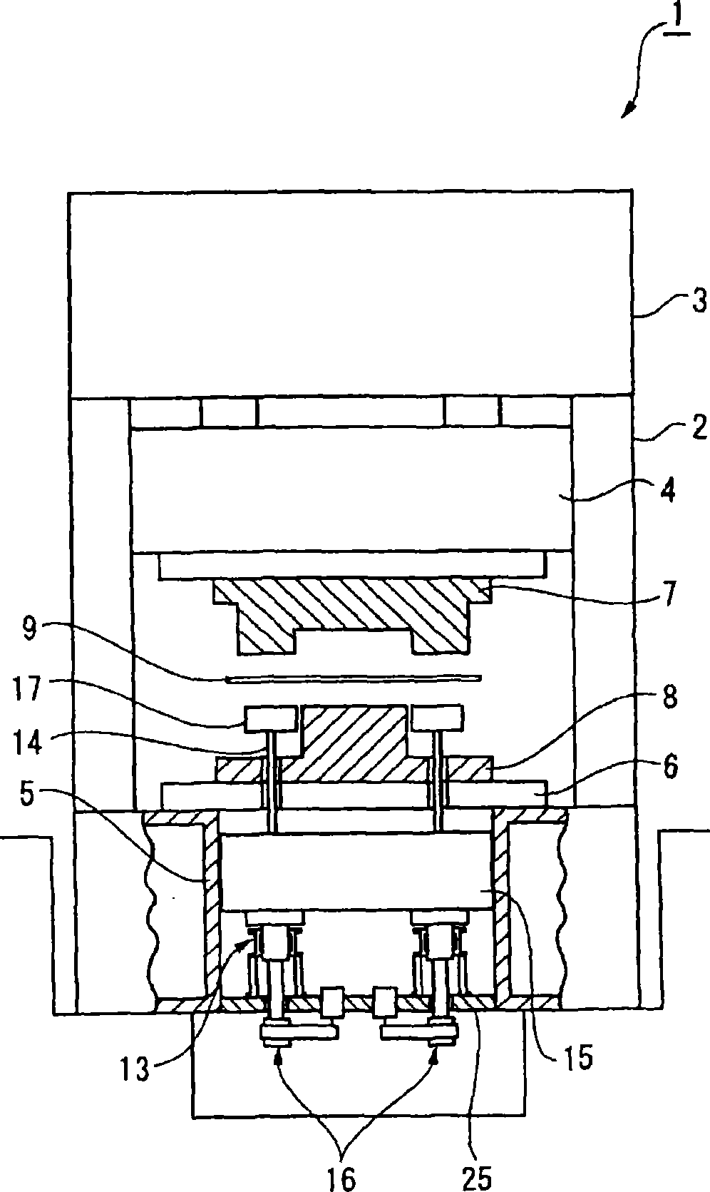
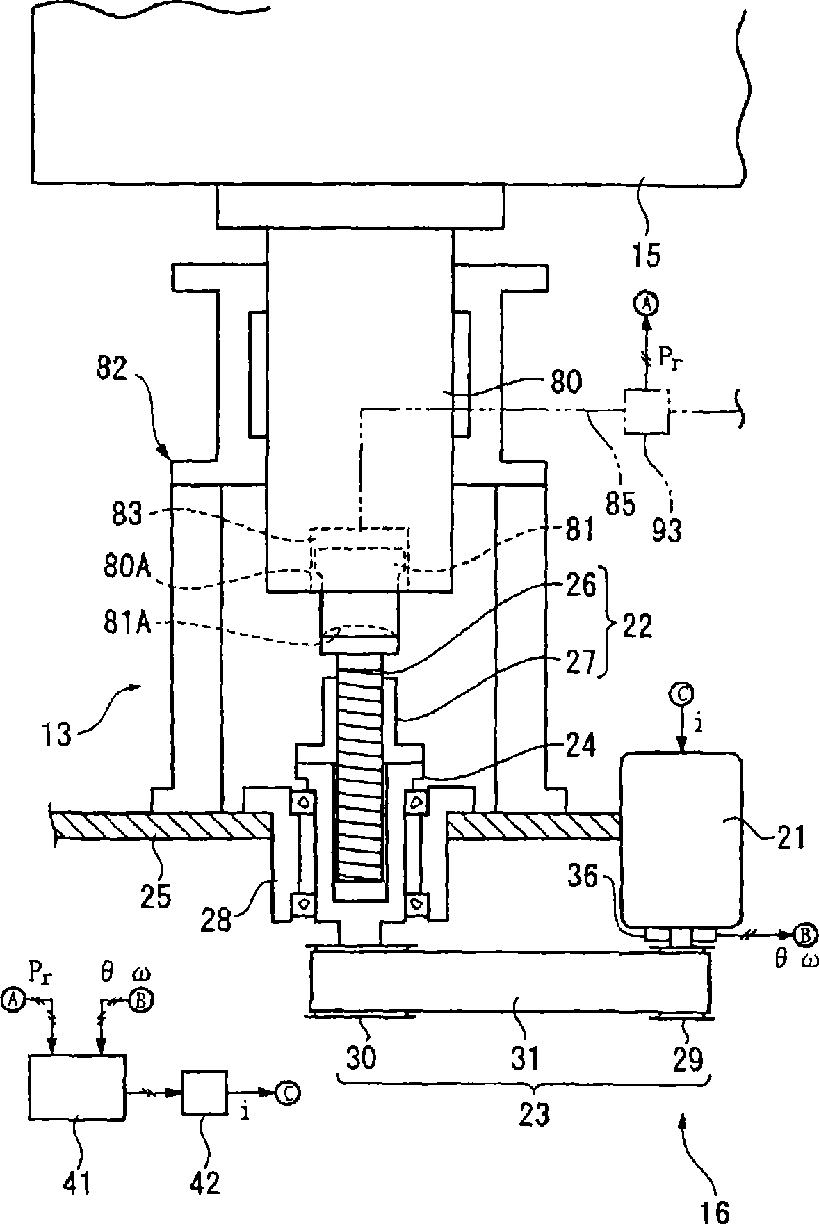
[0053] figure 1 A schematic configuration diagram showing a press machine according to an embodiment of the present invention. figure 2 A schematic configuration diagram showing the die cushion mechanism 13 of the first embodiment.

[0054] figure 1 The stamping machine 1 shown has: a slider 4, which is freely supported on the main body frame 2, and driven up and down by the slider driving mechanism 3; a backing plate 6, which is arranged opposite to the slider 4 and installed on the bed 5 superior. An upper mold 7 is installed on the lower surface of the slider 4 , and a lower mold 8 is installed on the upper surface of the backing plate 6 . In this manner, press working (drawing) is performed on the workpiece 9 arranged between the upper die 7 and the lower die 8 by the lifting operation of the slider 4 .

[0055...


PUM


Abstract

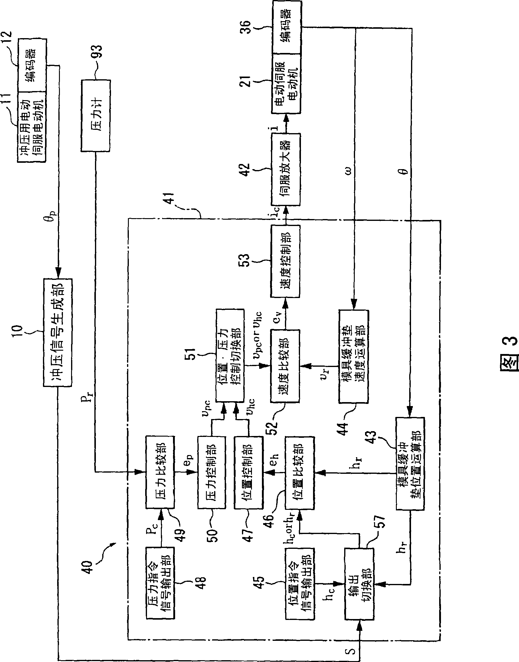
A press die cushion controller includes: a position instruction signal output unit (45) for outputting a die cushion pad position instruction signal; position detection means (36) for detecting the position of die cushion pad; a position comparison unit (46) for outputting a position deviation signal in accordance with a deviation of a target position value based on the position instruction signal from the position detection value based on the position detection signal; a position control unit (47) for outputting a position speed instruction signal based on the position deviation signal; a speed control unit (53) for outputting a motor current instruction signal in accordance with the position speed instruction signal from the position control unit (47); a servo amplifier (42) for generating current in accordance with a motor current instruction signal; and an output switching unit (57) for switching the position detection signal from the position detection means (36) to the position instruction signal from the position instruction output unit (45) according to the press signal when the slide has reached the bottom dead center.

Description

technical field [0001] The present invention relates to a die cushion mechanism control device, which is a die cushion mechanism control device used in stamping machines such as drawing processing, and controls the movement of a die cushion in synchronization with the movement of a slider. Background technique [0002] Conventionally, a control device proposed in Patent Document 1 is known, for example, as a die cushion mechanism control device that controls the lifting operation of a die cushion driven by a servo motor. In the die cushion mechanism control device of Patent Document 1, the cushion stroke of the die cushion mechanism is controlled by position control before the upper die of the slider clamps the workpiece and contacts the die cushion pad. When the current change of the servo motor when the load starts to act on the die cushion is detected, position control is switched to pressure control based on the detection signal of the current change, and a preset cushio...

Claims


Application Information

Patent Timeline
Patent Type & Authority Patents(China)
IPC IPC(8): B21D24/02
CPCB21D24/10G05B19/19G05B2219/42094
Inventor 铃木裕一
Owner KOMATSU SANKI
Learn More