Method and apparatus for determining target district

A technology of target cells and adjacent cells, applied in the directions of access restriction, electrical components, wireless communication, etc., can solve the problem of many handovers and so on

Inactive Publication Date: 2009-05-27
HUAWEI TECH CO LTD
View PDF0 Cites 40 Cited by
  • Summary
  • Abstract
  • Description
  • Claims
  • Application Information

AI Technical Summary

Problems solved by technology

[0005] Embodiments of the present invention provide a method and device for determining a target cell to solve the problem of too many handovers in the handover process of the target cell when the UE is in motion

Method used


Image

  • Method and apparatus for determining target district
  • Method and apparatus for determining target district
  • Method and apparatus for determining target district

Examples


Embodiment 1

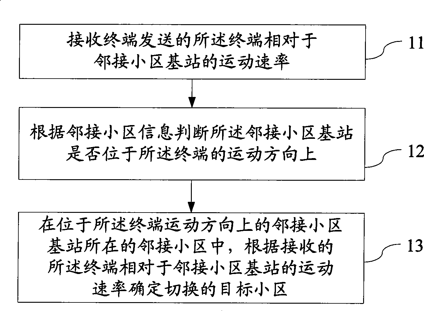
[0033] like figure 1 As shown, the embodiment of the present invention provides a method for determining a target cell, including:

[0034] 11. Receive the movement rate of the terminal relative to the base station of the adjacent cell sent by the terminal;

[0035] Wherein, the moving rate of the terminal relative to the adjacent cell is the magnitude of the velocity component of the moving speed of the terminal in the direction of the connection between the terminal and the base station of the adjacent cell.

[0036] 12. Judging whether the base station of the adjacent cell is located in the moving direction of the terminal according to the information of the adjacent cell;

[0037] Wherein, the adjacent cell information may be sent by the UE, and the adjacent cell information may include but not limited to the reference signal reporting power value of the adjacent cell, the reference signal reporting quality value and the distance between the terminal and the adjacent cell...

Embodiment 2

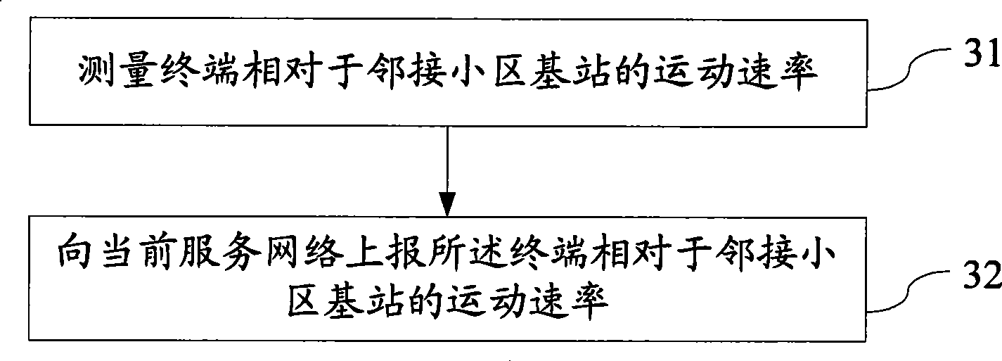
[0046] like image 3 As shown, the embodiment of the present invention provides a method for determining a target cell, including:

[0047] 31. Measure the movement rate of the terminal relative to the base station of the adjacent cell;

[0048] 32. Send the movement rate of the terminal relative to the base station of the adjacent cell to the current serving network.

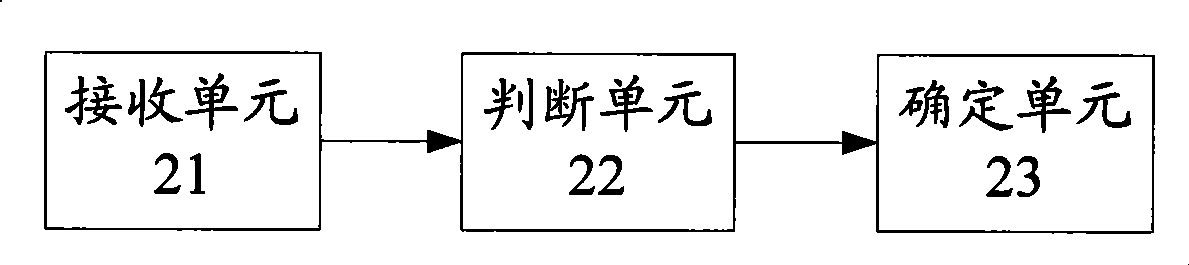
[0049] In order to better implement the above-mentioned method for determining a target cell, an embodiment of the present invention also provides a terminal device, such as Figure 4 As shown, it includes a measurement unit 41 and a reporting unit 42; wherein,

[0050] The measuring unit 41 is used to measure the movement rate of the terminal relative to the base station of the adjacent cell;

[0051] The reporting unit 42 is configured to send the movement rate of the terminal relative to the base station of an adjacent cell obtained by the measuring unit 41 to the current serving network.

[0052] The me...

Embodiment 3

[0054] like Figure 5 As shown, the embodiment of the present invention provides a method for determining a target cell, which specifically includes the following steps:

[0055] 51. The current serving base station sends a rate measurement request to the UE.

[0056] The manner in which the current serving base station delivers the rate measurement request to the UE may be to deliver a special rate measurement request message, or carry the rate measurement request through a measurement control message.

[0057] There is no information element that can carry the rate measurement request in the existing measurement control message, so a rate measurement information element can be added to the measurement control request sent by the current serving base station to the UE to carry the rate measurement request signaling.

[0058] 52. The UE measures its movement rate relative to the base station of the adjacent cell, and the movement rate is the magnitude of the velocity component...


PUM


Abstract

The embodiment of the invention discloses a method and device for determining target cell, relating to mobile communication technology field, means to solve problem of excessive switching times of target cell when UE is mobile. The method comprises: receiving terminal movement rate relative to adjacent cell base station transmitted by terminal; judging if the adjacent cell base station is located at movement direction of the terminal according to the adjacent cell information; determining switched target cell according to receiving terminal movement rate relative to adjacent cell base station in adjacent cell. Method and device provided by the embodiment of the invention is suitable for accurately positioning target cell under UE movement state.

Description

technical field [0001] The invention relates to mobile communication technology, in particular to a method and device for determining a target cell. Background technique [0002] At present, in the LTE (Long Time Evolution, long-term evolution) project, when the mobile terminal performs cell handover, the selection of the target cell is mainly based on the RSRP (Reference Signal Receive Power) of the UE (User Equipment, user equipment) to the target cell by the network side. Signal Received Power) or RSRQ (Reference Signal Receive Quality, reference signal received quality) measurement results, combined with the neighboring cell relationship between the serving cell and the target cell to select an appropriate target cell for the UE; generally speaking, in the prior art Both directly take the cell corresponding to the maximum value of RSRP or RSRQ reported by the UE as the preferred target cell. [0003] In the process of realizing the above-mentioned target cell handover, ...

Claims


Application Information

Patent Timeline
Patent Type & Authority Applications(China)
IPC IPC(8): H04W36/30H04W36/32
CPCH04W48/20H04W8/24H04W36/08H04W64/006
Inventor 李剑波
Owner HUAWEI TECH CO LTD
Why Eureka
Try Eureka