Electronic apparatus
A technology for electronic equipment and circuit boards, applied in circuits, electrical components, electrical solid devices, etc., and can solve problems such as large cooling structures
- Summary
- Abstract
- Description
- Claims
- Application Information
AI Technical Summary
Problems solved by technology
Method used
Image

Examples
no. 1 example
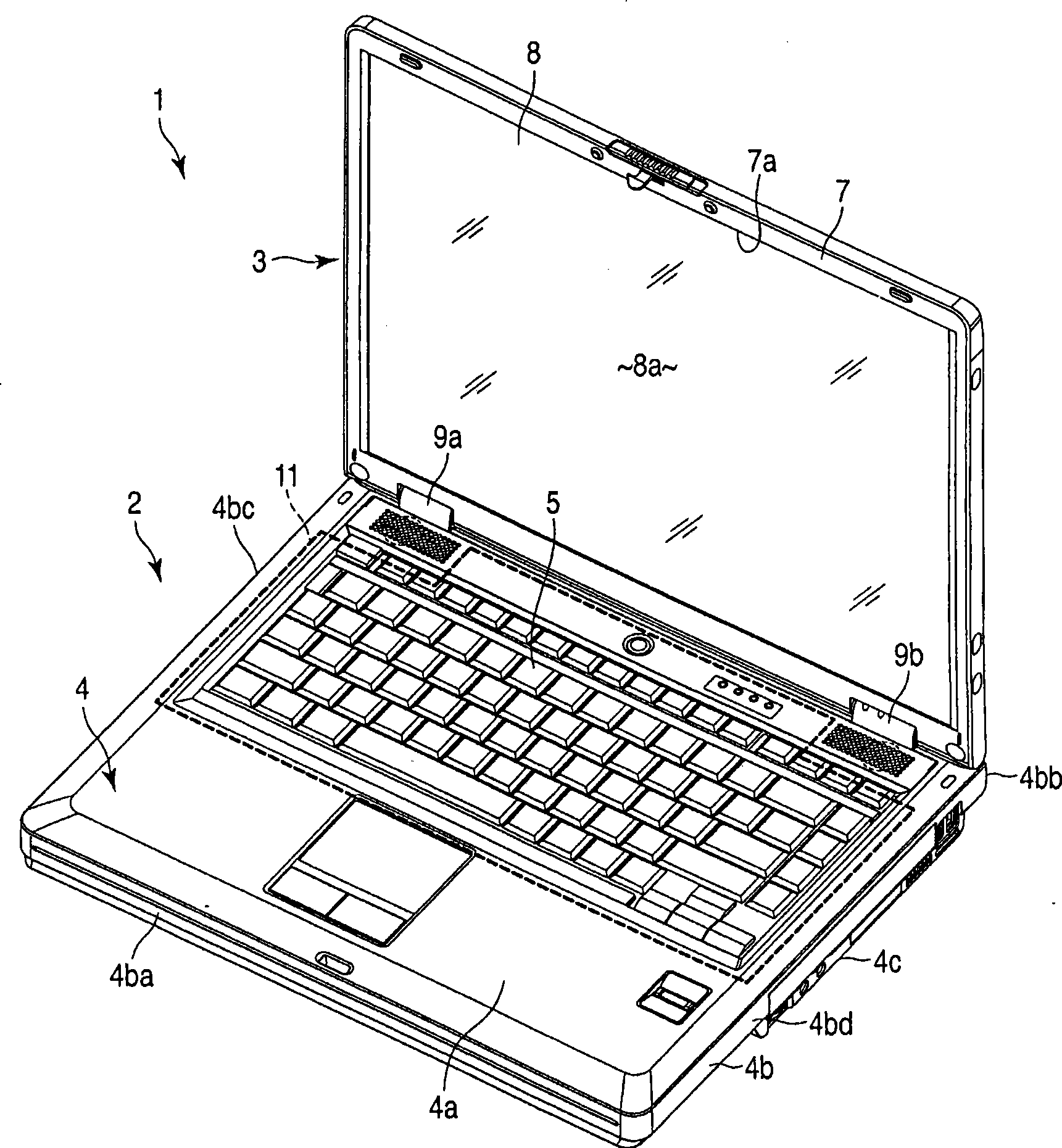
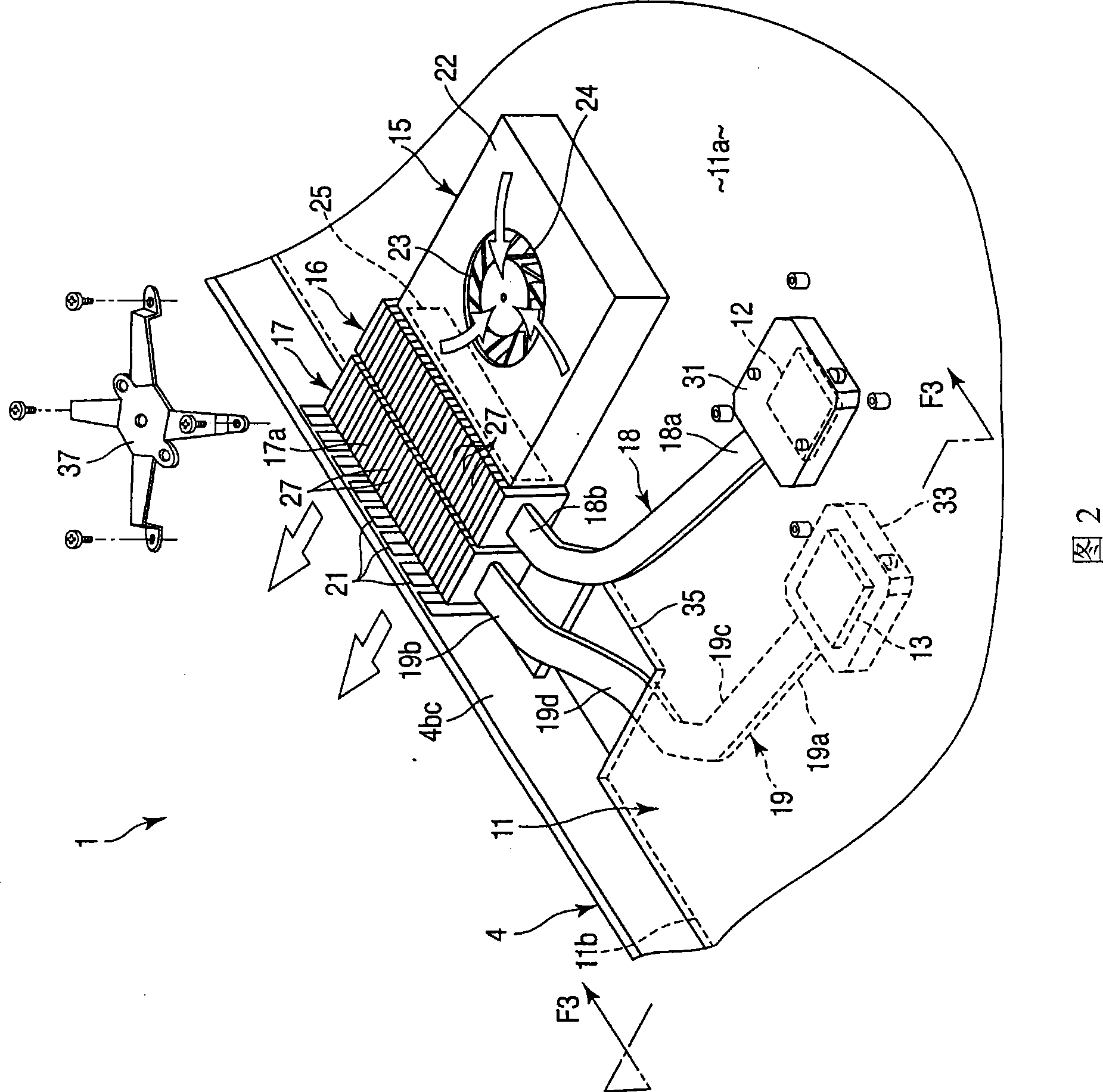
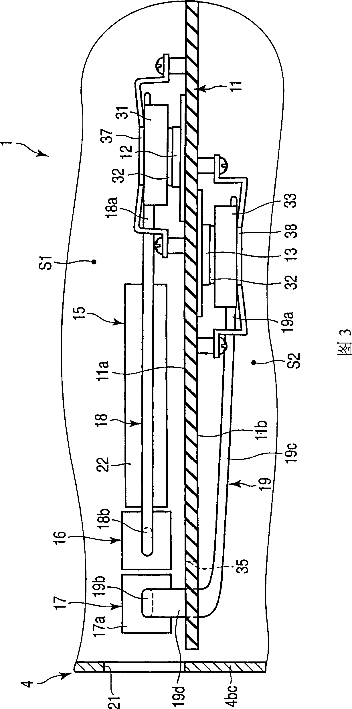
[0024] figure 1 to 3 disclose the portable computer 1 as the electronic device according to the first embodiment of the present invention. Such as figure 1 As shown, the portable computer 1 includes a main body 2 and a display unit 3 .
[0025] The main body 2 has a frame body 4 formed like a box. The frame body 4 has a top wall 4a, a side wall 4b, and a bottom wall 4c. The top wall 4a supports the keyboard 5 . The side walls 4b include a front side wall 4ba, a rear side wall 4bb, a right side wall 4bc, and a left side wall 4bd. The front side wall 4ba is a wall portion facing the user. The rear side wall 4bb is a wall portion facing in the direction opposite to the user.
[0026] The display unit 3 includes a display housing 7 and a display device 8 included in the display housing 7 . The display device 8 has a display screen 8a. The display screen 8 a is exposed to the outside of the display frame 7 through the opening 7 a in the front surface of the display frame 7 ...
no. 2 example
[0068] Now, will refer to Figure 4 A portable computer 1 is explained as an electronic device according to a second embodiment of the present invention. Structures of the second embodiment having the same or similar functions as the corresponding structures of the first embodiment are denoted by the same reference numerals and will not be described below.
[0069] The circuit board 11 according to the present embodiment is not equipped with a cutout through which the second heat pipe 19 passes. The second heat pipe 19 extends to go around the periphery of the circuit board 11 . Specifically, the circuit board 11 has a first edge portion 41 opposite to the right side wall 4bc in which the exhaust hole 21 is formed, and a second edge adjacent to the first edge portion 41 and opposite to, for example, the front side wall 4ba. Section 42.
[0070]The second heat pipe 19 extends to a region away from the circuit board 11 , and then in the region away from the circuit board 11 ,...
no. 3 example
[0073] Now, a portable computer 1 as an electronic device according to a third embodiment of the present invention will be described with reference to FIGS. 5 and 6 . Structures of the third embodiment having the same or similar functions as the corresponding structures of the first embodiment are denoted by the same reference numerals and will not be described below.
[0074] As shown in FIGS. 5 and 6 , the second heat dissipation member 17 according to the present embodiment is provided outside the area of the circuit board 11 . The circuit board 11 is not equipped with a cutout through which the second heat pipe 19 passes.
[0075] The second heat pipe 19 extends to a region away from the circuit board 11 , and then, in the region away from the circuit board 11 , slopes toward a region opposite to the circuit board 11 and opposite to the second heating element 13 . The remaining structure of the portable computer 1 of the third embodiment is the same as that of the first...
PUM
 Abstract
Description
Claims
Application Information
 - R&D
- Intellectual Property
- Life Sciences
- Materials
- Tech Scout
- Unparalleled Data Quality
- Higher Quality Content
- 60% Fewer Hallucinations
Browse by: Latest US Patents, China's latest patents, Technical Efficacy Thesaurus, Application Domain, Technology Topic, Popular Technical Reports.
© 2025 PatSnap. All rights reserved.Legal|Privacy policy|Modern Slavery Act Transparency Statement|Sitemap|About US| Contact US: help@patsnap.com