Supercharge Your Innovation With Domain-Expert AI Agents!

Single-windmill, single-motor, vertical-wheel and multi-stage wind power tower

A single-motor, windmill technology, applied to wind power generator components, wind power generation, wind power generators at right angles to the wind direction, etc., can solve the problem that the vertical axis power generation mode cannot become the main force of wind power generation equipment, the vertical axis of power is weakened, and the vertical axis Self-heavy and other problems, to achieve the effect of avoiding the reduction of power generation, saving equipment investment, and improving the utilization rate of wind energy

Inactive Publication Date: 2009-06-03
乔飞飞
View PDF0 Cites 6 Cited by
  • Summary
  • Abstract
  • Description
  • Claims
  • Application Information

AI Technical Summary

Problems solved by technology

[0002] Wind power generation equipment in the world today mainly has vertical axis and horizontal axis power generation methods; vertical axis blades are mainly single-supported vertical blades; due to design defects, vertical axis blades rotate at the same part when generating power, The vertical axis is too heavy, so the power is weakened by the vertical axis, so that the vertical axis cannot maximize the effect of using wind power to generate electricity. This is also the main reason why the vertical axis is not favored by developers and users, especially This design does not make full use of wind energy, so that the vertical axis power generation mode cannot become the main force of wind power generation equipment; I have found through research that if the technical problem of continuous shaft rotation can be solved, the power generated by the vertical axis should be due to the horizontal axis, especially without looking for windward noodle

Method used


Image

  • Single-windmill, single-motor, vertical-wheel and multi-stage wind power tower
  • Single-windmill, single-motor, vertical-wheel and multi-stage wind power tower
  • Single-windmill, single-motor, vertical-wheel and multi-stage wind power tower

Examples


Embodiment Construction

[0019] The present invention can be explained in more detail with reference to the following examples; however, the present invention is not limited to the combination of these examples.

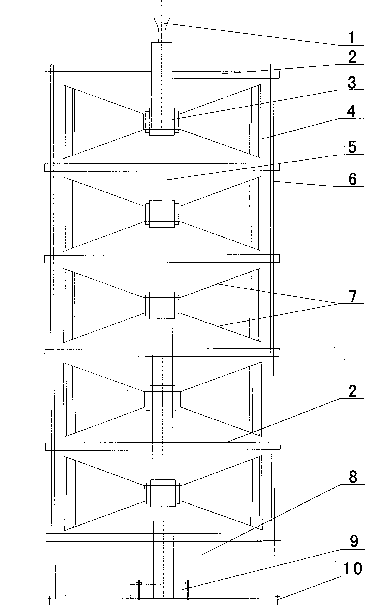
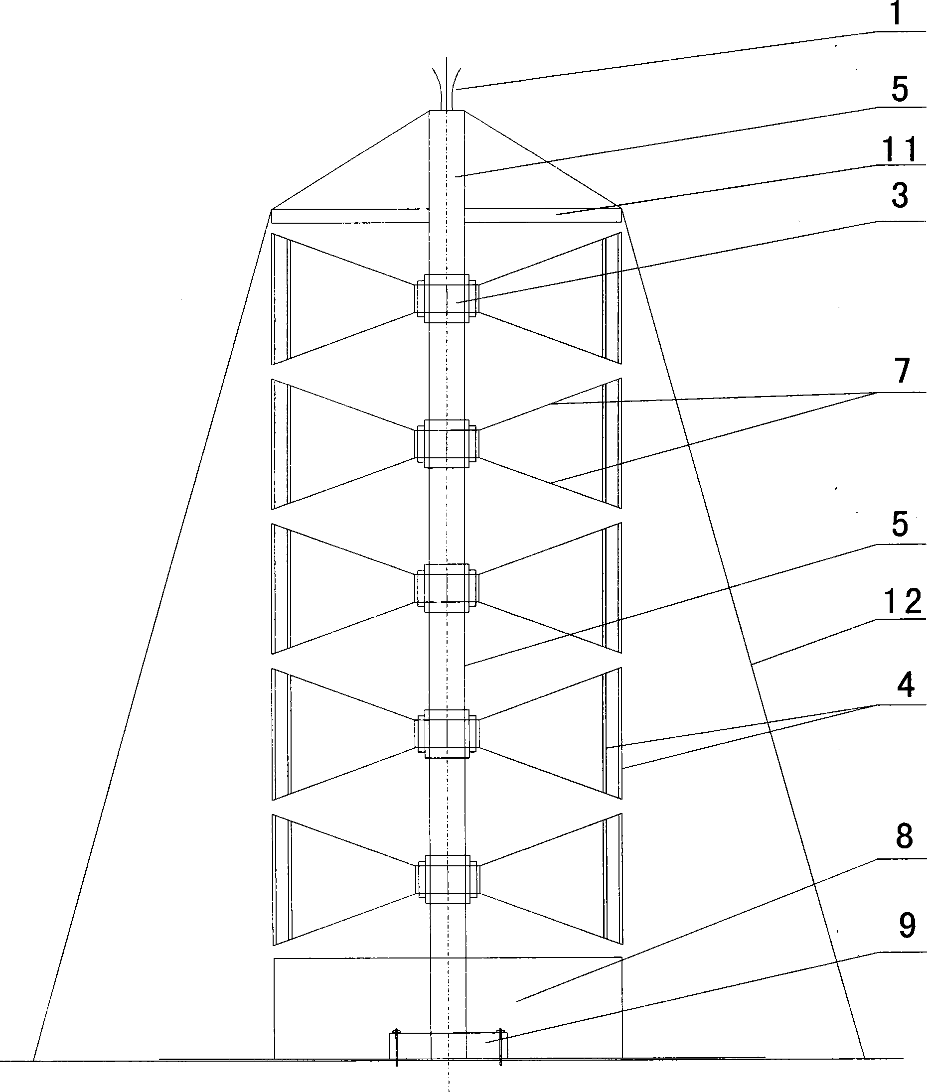
[0020] exist figure 1 , 2 , 3, 4, 5 or one of a single windmill single motor vertical wheel multi-stage wind power tower, including the wind blade 4 structure for absorbing wind energy, the generator 3 structure for power generation, and the multi-layer power generation structure for series connection Central cylinder 5; the structure of the blade 4 for absorbing wind energy includes the blade 4 and the connecting rod 7 of the blade, and the upper and lower ends of the blade 4 are respectively connected to the outer ends of the connecting rod 7 of the blade. The outer rotor sleeve of the machine 3 is provided with a link structure connecting the inner end of the fan blade connecting rod 7, and the central column 5 runs through the center of the stator of the generator 3 to form a set of win...


PUM


Abstract

The invention relates to a single-windmill, single-motor, vertical-wheel and multi-stage wind power tower, which belongs to the technical field of the wind power generation equipment. The fan blade (4) for absorbing wind energy, which structurally comprises a fan blade (4) and a fan blade connecting rod (7), wherein the upper end and the lower end of the fan blade (4) are respectively connected at the outer end of the fan blade connecting rod (7); a link structure connected at the inner end of the fan blade connecting rod (7) is sleeved on an outer rotor of the power generator (3); a center cylinder (3) penetrates the center of a stator of the power generator (3), so that a set of wind power generation mechanism is formed. By adopting the technical proposal that the spindle of the power generator adopts a hollow structure and the stator of the power generator is fixed on the centre cylinder, the invention realizes that only one rotor rotates when the fan blade rotates, and the cylinder and the stator are fixed. Therefore, the load of the fan blade is effectively redcued so as to realize the purpose of maximizing wind power utilization.

Description

technical field [0001] The invention belongs to the technical field of wind power generation equipment, and in particular relates to a single windmill and single motor vertical wheel power generation structure, and a multi-stage wind power generation tower formed by stacking and combining the structures. Background technique [0002] Wind power generation equipment in the world today mainly has vertical axis and horizontal axis power generation methods; vertical axis blades are mainly single-supported vertical blades; due to design defects, vertical axis blades rotate at the same part when generating power, The vertical axis is too heavy, so the power is weakened by the vertical axis, so that the vertical axis cannot maximize the effect of using wind power to generate electricity. This is also the main reason why the vertical axis is not favored by developers and users, especially This design does not make full use of wind energy, so that the vertical axis power generation m...

Claims


Application Information

Patent Timeline
Patent Type & Authority Applications(China)
IPC IPC(8): F03D9/00F03D3/06F03D11/00H01T19/04F03D9/25F03D13/20F03D80/30
CPCY02E10/74Y02E10/72Y02E10/728
Inventor 乔飞飞乔飞阳乔晖照曹润芳
Owner 乔飞飞
Features
  • R&D
  • Intellectual Property
  • Life Sciences
  • Materials
  • Tech Scout
  • Unparalleled Data Quality
  • Higher Quality Content
  • 60% Fewer Hallucinations
Learn More