

Socket unit
A socket and light source unit technology, which is applied to electrical components, two-part connection devices, coupling devices, etc., can solve the problem that the working state of the socket is not considered.
- Summary
- Abstract
- Description
- Claims
- Application Information
AI Technical Summary
Problems solved by technology
Method used
Image

Examples
Embodiment Construction
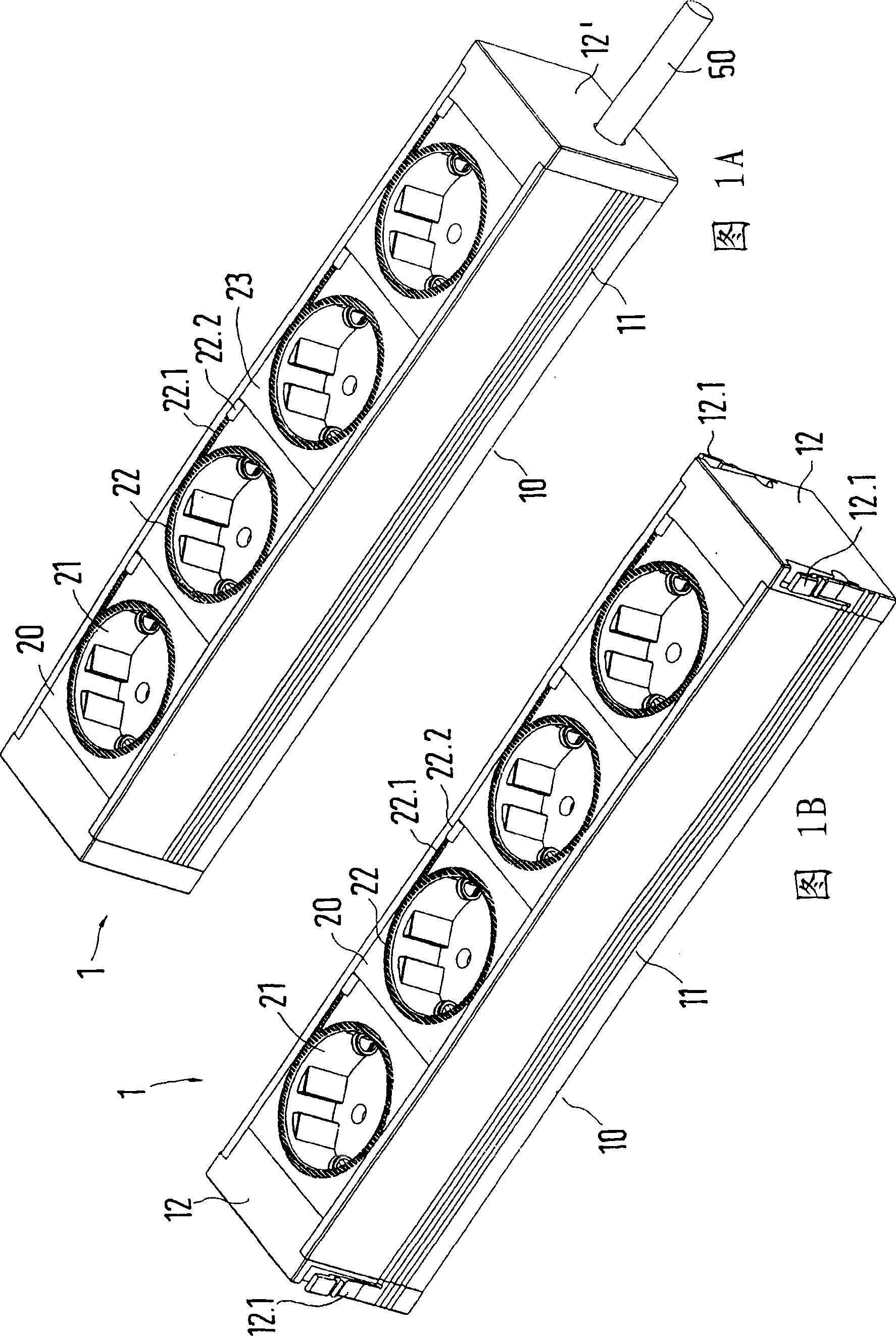
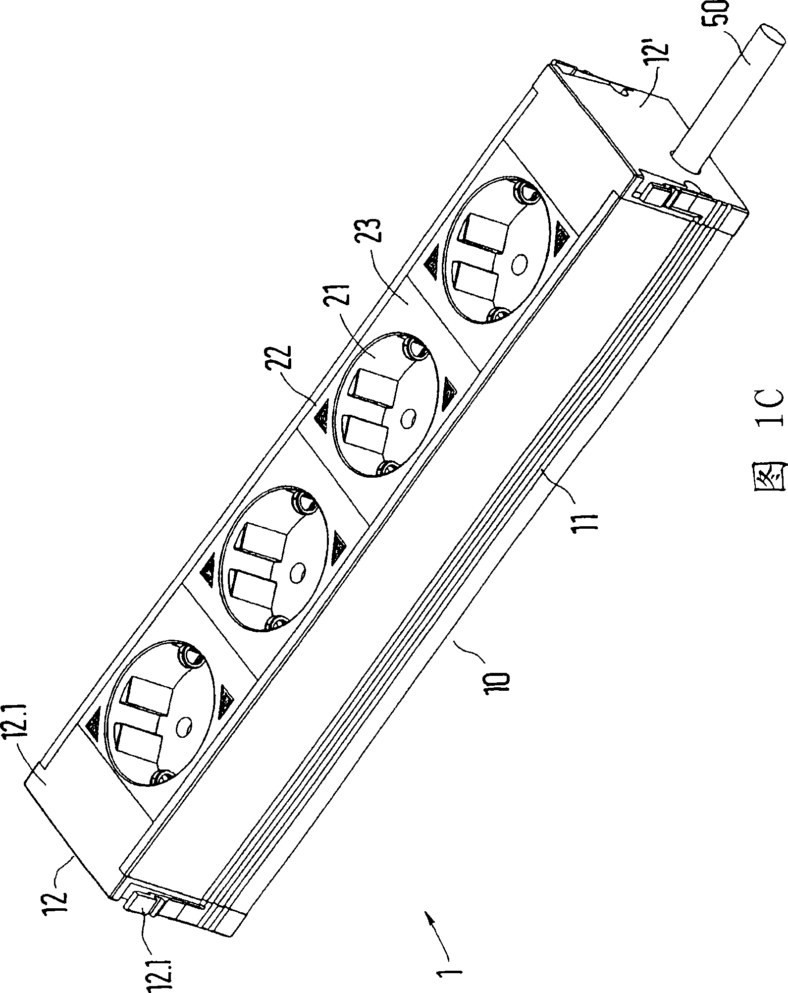
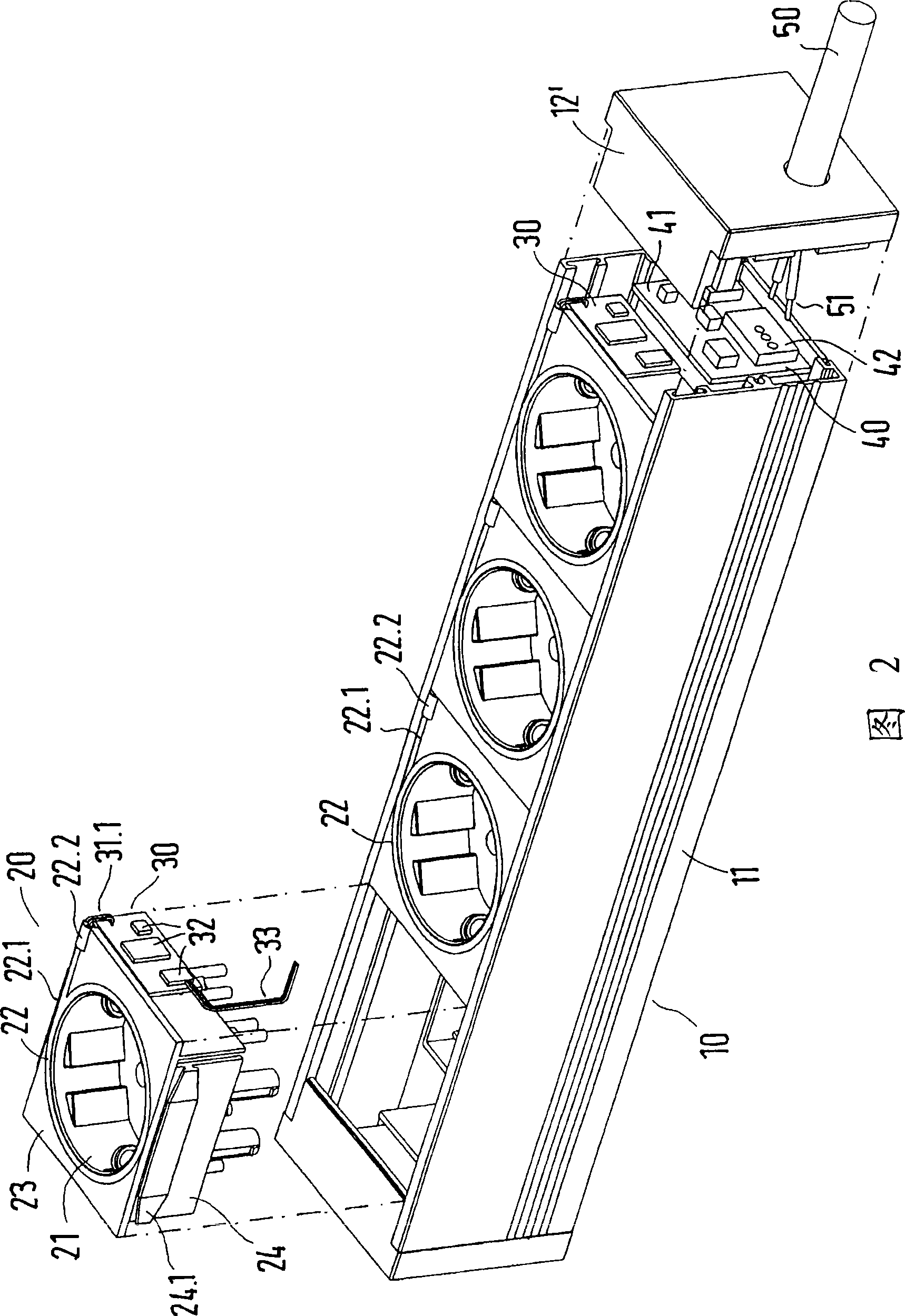
[0024] FIG. 1A shows a socket unit 1 in the form of a plug strip, which has a plurality (four in the figure) of socket inserts 20 mounted next to one another in the housing 10 of the socket unit 1 . The housing 10 is U-shaped in cross-section with side walls 11, a base plate and end wall elements 12' and an open upper side, on which the socket insert 20 and the mutually adjoining cover wall 23 are mounted. At the same time, the open upper side of the housing 10 is completely covered by the cover wall 23, with which the upper face section of the end wall element 12' adjoins at both ends of the housing 10. In one of the end wall elements 12' there is provided a through hole for a power supply cable 50, in particular a power supply cable. The socket inserts 20 each have a socket 21 for inserting a plug by a user. Each slot 21 is surrounded by an annular luminous indicator 22, and the luminous indicator becomes a lead wire 22.1 extending tangentially along the longitudinal direct...
PUM
 Abstract
Description
Claims
Application Information