
crane

A crane and frame technology, applied in the field of cranes, can solve problems such as not being obtained, and achieve the effects of optimal utilization, good stability, and correcting the push-out length.

Active Publication Date: 2021-05-28
ВАЛТЕР БИЕДЕНБАХ
View PDF8 Cites 0 Cited by
  • Summary
  • Abstract
  • Description
  • Claims
  • Application Information

AI Technical Summary

Problems solved by technology

However, no suggestion is drawn that the individual ejectors should be ejected one after the other starting with the lowest ejector

Method used


Image

  • crane

Examples


Embodiment Construction

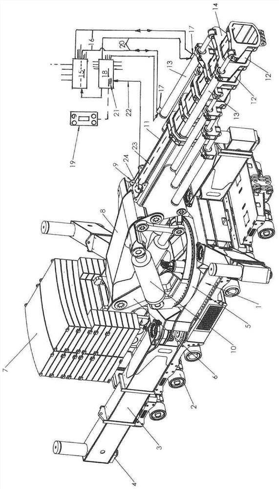
[0018]The main application field of the present invention is a so-called heavy-duty crane which is loaded into the transport vehicle on a longer distance and unloading from the transport vehicle and can be rolled or movable there in its own walking mechanism. .

[0019]The crane shown in the drawings has a bed shaped rack 1, which is received on the roller 2 and can be rolled, and the roller can be equipped with a heavy-duty tire. In order to improve the safety of the anti-tipping, the rack 1 is equipped with a scalable beam 3 in the example described, and the support beam is pivotally supported around the vertical axis in the region of the rack angle. The upper and in its free end is disposed with a support pin 4 on the foundation, the support pin can be removed or can be formed by such a hydraulic cylinder by means of a hydraulic cylinder configuration.

[0020]A base 6 that rotatably rotatable around the rotary flange 5 is provided on the rack 1, and on the one hand, the ballast is sus...


PUM


Abstract

The invention relates to a crane comprising a frame on which is provided a rotatable frame on which a telescopic pivotable boom is received, the boom having a plurality of Movable push-out parts, said push-out parts can be moved out and moved in by means of a hydraulic drive, the cantilever is equipped with a travel measuring device for measuring the length of removal, which is connected to the control device, at each length, all push-out parts can be moved out of their maximum A correspondingly configured portion of the length is removed, thereby achieving high stability and load-carrying capacity: each push-out is assigned a hydraulic cylinder arrangement, which can be actuated independently of the remaining hydraulic cylinder arrangements and stored in the control unit There is a removal program, which is designed so that all ejectors can be removed individually one after the other, said removal program includes a follow-up control, according to which the extension of the boom begins with the removal of the lowermost ejector and continues upwards in succession .

Description

Technical field[0001]The present invention relates to a crane, in particular a heavy-duty crane, which includes a rack, and a spherbier around the vertical axis is disposed on the frame, which is scalable, a pivotable cantilever, which is pivotable around the horizontal axis. On the base, the cantilever has a plurality of launched portions that can be moved in the axial direction to each other, the launch portion removed and removing in the hydraulic drive, wherein the scalable cantilever is arranged. It shifted the length of the stroke measuring device, the stroke measuring device and the input end of the control device configured to the hydraulic pressure drive, the desired removal length of the cantilever can be input to the control device, wherein at each desirable cantilever In the case of the length, all the launched portions removed the corresponding part of the corresponding configuration of their maximum shift length.Background technique[0002]A crane is obtained from DE 196...

Claims


Application Information

Patent Timeline
Patent Type & Authority Patents(China)
IPC IPC(8): B66C23/693
CPCB66C23/705B66C2700/0392
Inventor 瓦尔特·比登巴赫
Owner ВАЛТЕР БИЕДЕНБАХ
Learn More