
Three-phase linkage type electrical switch

A three-phase linkage, electrical switch technology, applied in electrical switches, air switch parts, electrical components, etc., can solve the problem of not accurately reflecting the opening and closing status of the main body of the non-mechanical phase switch.

Pending Publication Date: 2021-04-27
HENAN PINGGAO ELECTRIC +2
View PDF8 Cites 0 Cited by
  • Summary
  • Abstract
  • Description
  • Claims
  • Application Information

AI Technical Summary

Problems solved by technology

[0005] The purpose of the present invention is to provide a three-phase linkage electric switch to solve the inaccuracy in the prior art when only relying on the opening and closing indication device on the mechanism box to display the opening and closing status of the three-phase linkage electric switch. Reflecting the technical problem of the opening and closing state of the main body of the non-mechanism phase switch

Method used


Image

  • Three-phase linkage type electrical switch
  • Three-phase linkage type electrical switch
  • Three-phase linkage type electrical switch

Examples


Embodiment 1

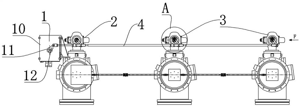
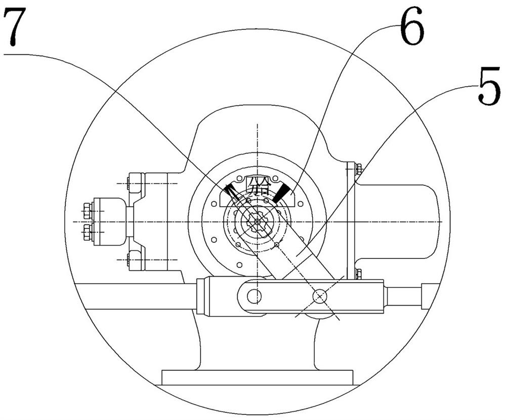
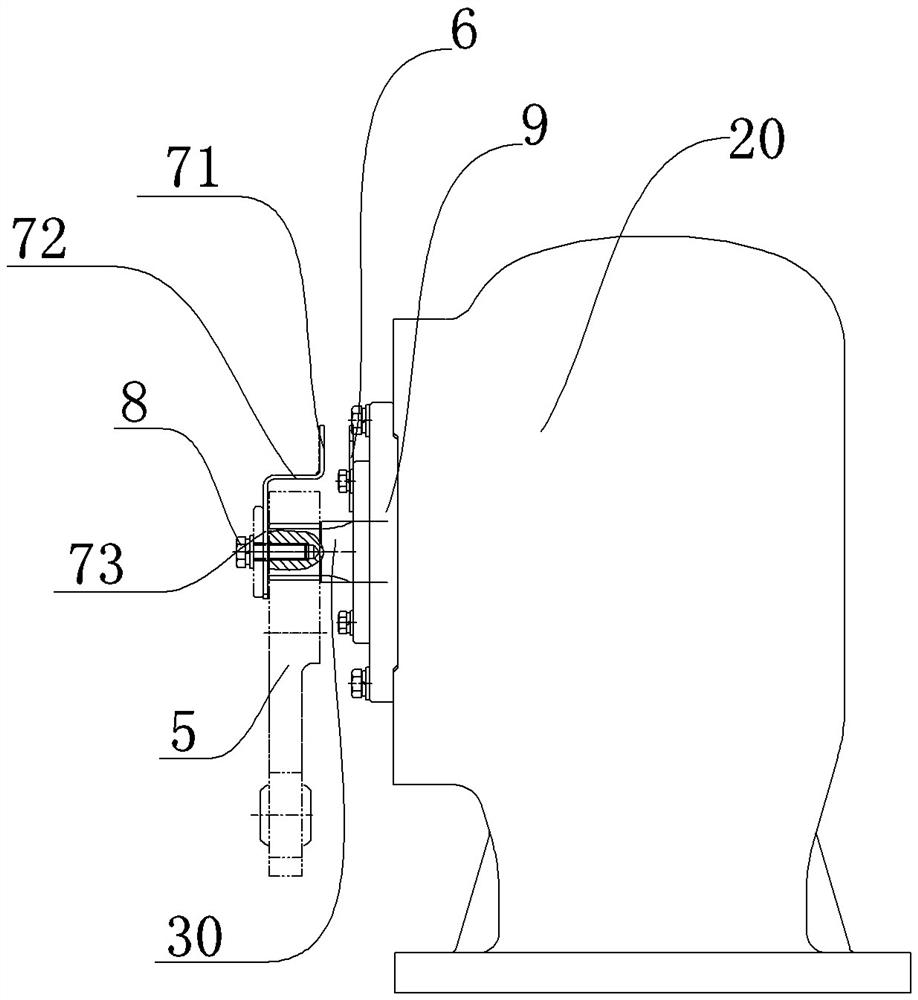
[0046] The structure of the three-phase linkage electrical switch is as follows: Figure 1 to Figure 4 As shown, the three-phase linkage electrical switch in this embodiment is an isolating switch, which includes a three-phase switch main body arranged in separate boxes, and the three-phase switch main bodies are distributed sequentially in the horizontal plane. The switch housing 20 is provided with dynamic and static contacts respectively to form a breaking structure. The power input shaft 30 is sealed and penetrated on the switch housing 20, and a dustproof cover 9 is set on the power input shaft 30. The power input here The shaft 30 is used to connect the connecting rod transmission mechanism 4 to input driving force to the main body of the three-phase switch to realize the opening and closing operation.

[0047] In this embodiment, an operating mechanism 1 is fixedly installed on one of the side phases of the three-phase switch main body, and the operating mechanism 1 is ...

specific Embodiment 2

[0056] The main difference between it and Embodiment 1 is that in Embodiment 1, a first opening and closing indicating device is provided on the mechanism box to display the opening and closing status of the main body of the mechanism phase switch. In this embodiment, a first opening and closing indicator device can be installed on the main body of the mechanism phase switch. At this time, the pointer can be fixedly installed on the power input shaft, and the opening and closing indicator board can be fixedly installed on the switch housing. At this time, a total of four opening and closing indicating devices are provided.

specific Embodiment 3

[0058] The difference between it and Embodiment 1 is that in Embodiment 1, in the second opening and closing indicating devices of the two non-mechanism phase switch main bodies, the pointer is fixedly installed on the power input shaft, and the opening and closing indicator board is fixedly installed on the corresponding on the switch housing. In this embodiment, the pointer can also be fixedly installed on the switch housing, and the opening and closing indicator board can be fixedly installed on the corresponding power input shaft. At this time, when the power input arm rotates with the power input shaft to realize When the opening and closing action, the opening and closing indicator will follow the rotation to realize the opening and closing indication.


PUM


Abstract

The invention relates to a three-phase linkage type electrical switch, and the switch comprises a three-phase switch main body which comprises a mechanism phase switch main body and two non-mechanism phase switch main bodies; an operating mechanism which is provided with a first opening and closing indicating device which is used for indicating the opening and closing states of the mechanism phase switch main body, wherein each non-mechanism phase switch main body is provided with a second opening and closing indication device used for indicating the opening and closing state of the corresponding non-mechanism phase switch main body. According to the three-phase linkage type electrical switch provided by the invention, the opening and closing states of the three-phase switch main body can be accurately displayed through the first opening and closing indicating device and the two second opening and closing indicating devices, so on-site inspectors can reliably observe the opening and closing states of each phase of switch main body, the problem that the opening and closing states are not clear due to non-mechanism phase transmission failure is solved, and safe operation of field products is guaranteed. The structure is reasonable in design, simple in structure, economical and practical, and adapts to the lean design requirement of the three-phase linkage type electrical switch.

Description

technical field [0001] The invention belongs to the technical field of electric switches, and in particular relates to a three-phase linkage electric switch. Background technique [0002] There are two transmission modes of three-phase mechanical linkage and electrical linkage for ultra-high voltage GIS isolating switch and grounding switch. The structure of the three-phase mechanically linked electrical switch is such as the earthing switch disclosed in the Chinese utility model patent whose authorized announcement number is CN201667505U. Realize the synchronous work of the three-phase switch body. [0003] For this type of three-phase electrical switch, it includes three single-phase switch bodies arranged in sequence in the horizontal plane, and the operating mechanism is usually set outside one of the side phases, so that the three single-phase switch bodies can be The main body of the mechanism phase switch and the main body of the non-mechanism phase switch are respe...

Claims


Application Information

Patent Timeline
Patent Type & Authority Applications(China)
IPC IPC(8): H01H9/16H01H31/02H01H31/10
CPCH01H9/16H01H31/026H01H31/10
Inventor 刘恩歌李美荣卢鹏刘超峰李雪曼张向娟王希郭浩杨向龙宋丽君
Owner HENAN PINGGAO ELECTRIC
Learn More