Wall hanging type device for trapping and killing winged insect

A wall-mounted, flying insect technology, applied in the field of flying insect traps, can solve the problems that the surface of the glue is easily covered by dust, the area of ​​the glue board is small, and the cost of prevention and control is high. handy effect

Inactive Publication Date: 2009-06-24
莫晓畅
View PDF6 Cites 9 Cited by
  • Summary
  • Abstract
  • Description
  • Claims
  • Application Information

AI Technical Summary

Problems solved by technology

These two types of products have certain defects. The way to kill flying insects with glue board is to use glue to stick the flying insects, and finally lead to the death of flying insects. The disadvantages of this type of products are: (1) The glue is easy to age under sunlight Loss of stickiness; (2) The surface of the glue is easily covered by dust, causing the glue board to fail to perform its normal function; (3) Due to the small area of ​​the glue board, it needs to be replaced frequently when the insect population density is high, so the control cost is high
The disadvantages of this patent are: there is no electric fan in the bracket, and the effect of luring and killing flying insects is not good enough

Method used


Image

  • Wall hanging type device for trapping and killing winged insect
  • Wall hanging type device for trapping and killing winged insect

Examples


Embodiment 1

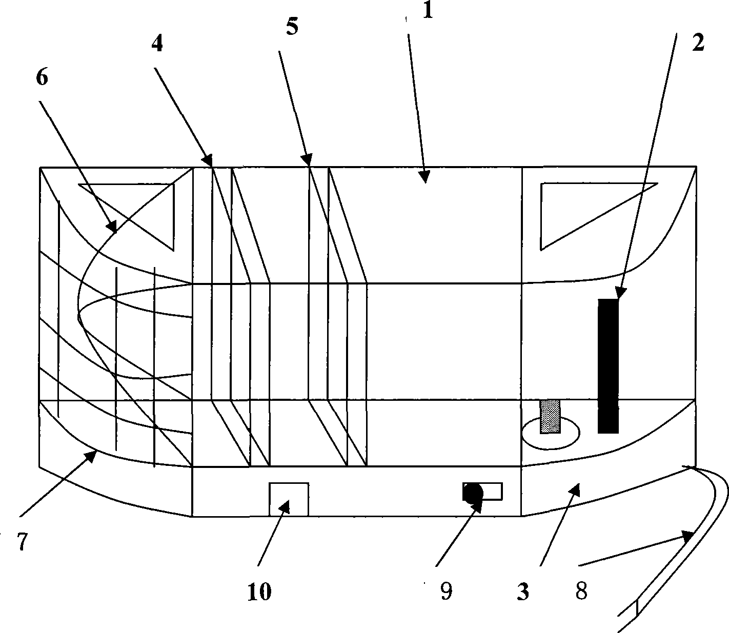
[0019] see figure 1 , a wall-mounted flying insect trap, including a casing 1 with openings at both ends of the left and right ends, the back of the casing 1 has a connecting piece hanging on the wall, and the right end of the casing is equipped with an attracting light source 2 and a In the container 3 containing the attractant, the other end of the housing is connected with a net bag 6 for collecting insects, and the middle part of the housing 1 is equipped with an exhaust fan 4 that sucks the wind from one end of the lure light source, and the direction of the exhaust fan 4 is to attract A safety fence 5 for shielding the exhaust fan is installed on one side of the light source, and a switch 9 is provided on the housing, and the switch 9 is connected to the power line 8 for attracting the light source 2 and the exhaust fan 4 at the same time.

[0020] The insect net bag 6 can be connected to the housing in a front and back drawable manner.

[0021] The wall-mounted flying ...

Embodiment 2

[0026] The difference between this embodiment and the first embodiment lies in that: the mouth of the insect-collecting net bag 6 is provided with a net door that can be opened and closed automatically, and the switch 9 is connected to the control circuit of the net door.

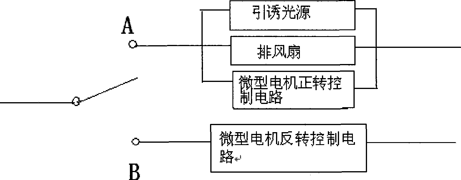
[0027] In this embodiment, a micromotor is arranged inside the wall-mounted flying insect trap, and the output shaft of the micromotor is connected to a rack-and-pinion transmission mechanism, and the rack in the rack-and-pinion transmission mechanism is connected to the net door. The output shaft of the micromotor can also be connected with a reduction mechanism (such as a gear reduction mechanism), so that the net door is slowly opened.

[0028] Such as figure 2 As shown, the switch described in this embodiment is a single-pole double-throw switch, and the switch blade is in the disconnected position in the initial state. A switching node is also connected to the forward rotation control circuit of the ...


PUM


Abstract

A wall hanging winged insect trap comprises a case with a right open and a left open, the back of the case is provided with a connecting piece hung on the wall, an inducing light source and a container filled with attractant are filled in one of the left end and a right end, an insect collecting bag is connected on the other end of the case, an exhaust fan for inducing wind from one end of the inducing light source is arranged in the middle of the case, a switch is arranged on the case, the switch is connected on power lines of the inducing light source and the exhaust fan. The invention provides a wall hanging winged insect trap which uses the fan for winding, has good insect-catching effect, and can be hung on the wall.

Description

(1) Technical field [0001] The invention relates to a flying insect trap. (2) Background technology [0002] Existing employing lure method to kill flying insects mainly contains two kinds of products at present, and a class is the device that uses sticky glue board, and another kind is the electric shock formula disinsection device. These two types of products have certain defects. The way to kill flying insects with glue board is to use glue to stick the flying insects, and finally lead to the death of flying insects. The disadvantages of this type of products are: (1) The glue is easy to age under sunlight Loss of stickiness; (2) The surface of the glue is easily covered by dust, causing the glue board to fail to perform its normal function; (3) Due to the small area of ​​the glue board, it needs to be replaced frequently when the insect population density is high, so the control cost is high . The electric shock type insect extermination device uses high-voltage electr...

Claims


Application Information

Patent Timeline
Patent Type & Authority Applications(China)
IPC IPC(8): A01M1/08A01M1/02
Inventor 莫晓畅
Owner 莫晓畅
Why Eureka
Try Eureka