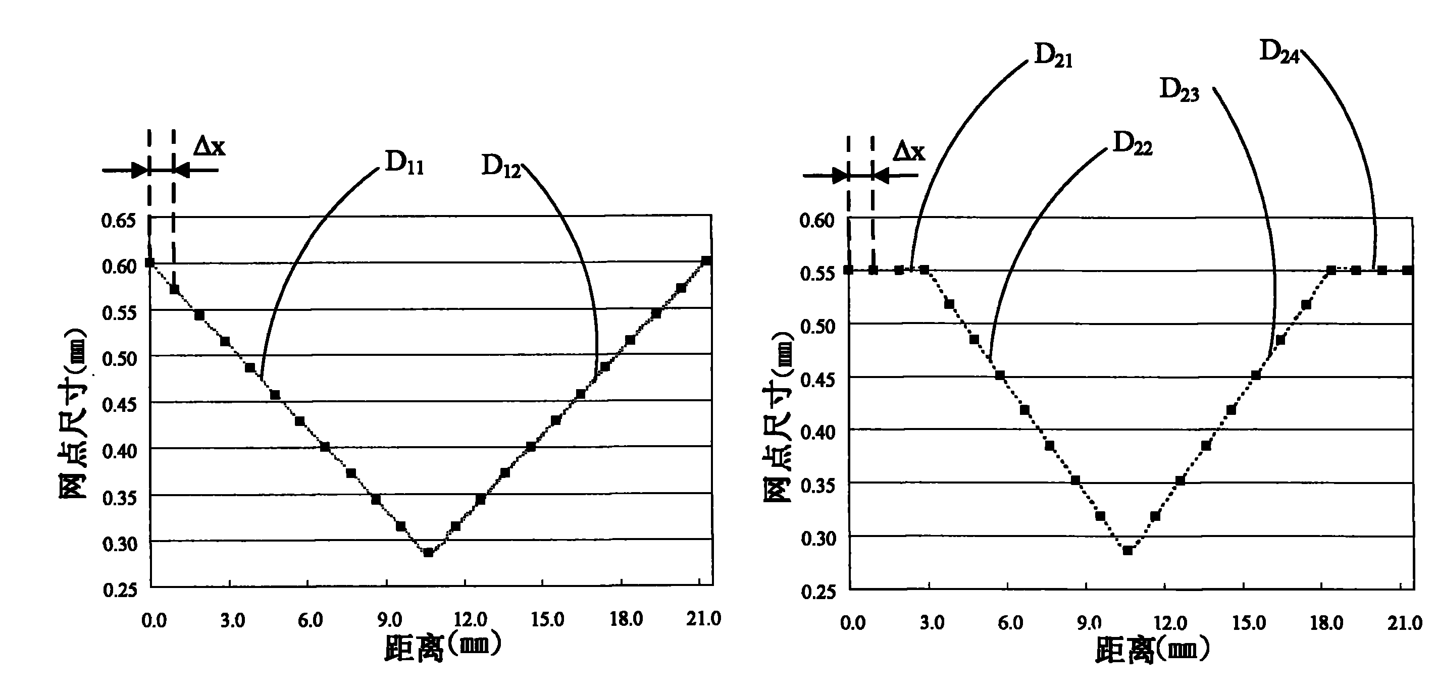
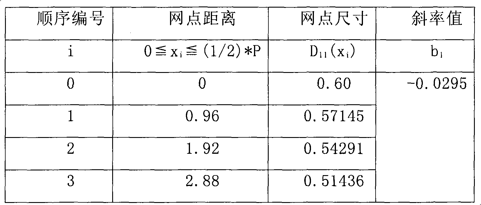
Backlight module with stipple pattern and its diffusing plate structure
A technology of backlight module and diffusion plate, which is applied in the field of backlight module and its diffusion plate structure, and the diffusion plate structure with dot pattern, which can solve the problems of low brightness percentage, rise, poor dark band stripes, etc., and achieve uneven brightness Effect
Inactive Publication Date: 2010-09-08
AU OPTRONICS CORP
View PDF0 Cites 0 Cited by
- Summary
- Abstract
- Description
- Claims
- Application Information
AI Technical Summary
Problems solved by technology
Due to the effect of multi-order curve function dots, in the vicinity of the light source positions of -21.3mm, 0mm, 21.3mm and 42.6mm, the brightness percentage corresponding to the light source drops sharply by about 12% compared with the C1 curve, and at -10.65mm , 10.65mm and 32mm, the brightness percentage corresponding to the light source increases by about 4%, and the overall brightness percentage change of the C2 curve is about 8%, although the dark band between the light source and the light source position has improved , but near the light source positions of -21.3mm, 0mm, 21.3mm and 42.6mm, the brightness percentage is significantly lower compared to other positions, as shown in the A1 area and A2 area, so at -21.3mm, 0mm where the light source is located , 21.3mm and 42.6mm above the position, but will form poor dark stripes (mura)
Method used
View moreImage
Smart ImageViewing Examples
Examples
Embodiment Construction
Login to View More PUM
 Abstract
The invention provides a backlight module with dot patterns and a diffuser plate structure thereof. The backlight module mainly consists of a reflector plate, a plurality of light sources and a diffuser plate. The light sources are arranged on the reflector plate with one light source space (P) to each other. The diffuser plate is arranged on the light source and keeps a distance of one mixed-light height (H) with the reflector plate. The diffuser plate includes dot patterns which possess a plurality of dots. The dots are arranged along the array direction of the light sources, and the size of the dots distributes according to a plurality of linear functions which are the functions of the light source space (P).
Description
【Technical field】 The present invention relates to a backlight module and its diffuser structure, in particular to a diffuser structure with dot patterns and a backlight module using the diffuser structure, which is suitable for liquid crystal displays. 【Background technique】 Due to the rapid development and progress of liquid crystal display technology, the application of liquid crystal displays is quite popular and widely used in various electronic products, such as computer screens and liquid crystal televisions. However, since the liquid crystal display is not a self-illuminating display, a backlight module is required to generate the backlight. In a direct light backlight module, the light sources are distributed and arranged between the diffuser plate and the reflection sheet. Generally speaking, when the backlight module is thinned or designed for energy saving, the backlight generated by the backlight module tends to have uneven brightness distribution due to the sm...
Claims
Login to View More Application Information
Patent Timeline
 Patent Type & Authority Patents(China)
IPC IPC(8): G02F1/13357G02B5/02F21Y101/02F21Y115/10
Inventor 林博瑛柯雅华林信吾
Owner AU OPTRONICS CORP
Features
- R&D
- Intellectual Property
- Life Sciences
- Materials
- Tech Scout
- Unparalleled Data Quality
- Higher Quality Content
- 60% Fewer Hallucinations
Learn More Browse by: Latest US Patents, China's latest patents, Technical Efficacy Thesaurus, Application Domain, Technology Topic, Popular Technical Reports.
© 2025 PatSnap. All rights reserved.Legal|Privacy policy|Modern Slavery Act Transparency Statement|Sitemap|About US| Contact US: help@patsnap.com


